

How to Install Synergy Heavy Duty Front Lower Control Arm Frame Brackets (07-18 Wrangler JK) on your Jeep Wrangler
Installation Time
3 hours
Tools Required
- Basic simple hand tools
- Quality jack & jackstands
- Metal cutting tools
- Angle grinder / cutting torch / sawzall / plasma cutter
- Grinding / sanding attachments
- Welding machine
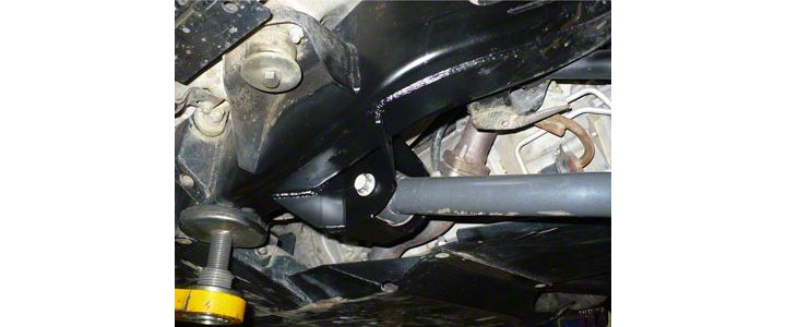
Shop Parts in this Guide
GENERAL NOTES:
• These instructions are also available on our website; www.synergymfg.com. Check the website before you begin for any updated instructions and additional photos for your reference.
• This is a weld on part and should be installed by an experienced welder.
• We recommend installing one side at a time.
• This part requires significant cutting & grinding of the factory control arm brackets.
• Be sure to disconnect the ground cable from the battery prior to welding as to prevent electrical damage to the vehicle.
PARTS LIST:
• 5021 JK FLCA FRAME BRACKET KIT
• (2) 5021-01 JK Front Lower Control Arm Frame Brackets (1L & 1R)
INSTALLATION:
1) Install one side at a time so that one side can be used as a reference to measure against.
2) Start on the passenger side as this side is easier to cut off.
3) Begin by removing the passenger front lower control arm. Once removed, safely raise the vehicle to a height that can easily be worked under. Allow the front suspension to hang free and safely support the vehicle with a quality jack and jack-stands.
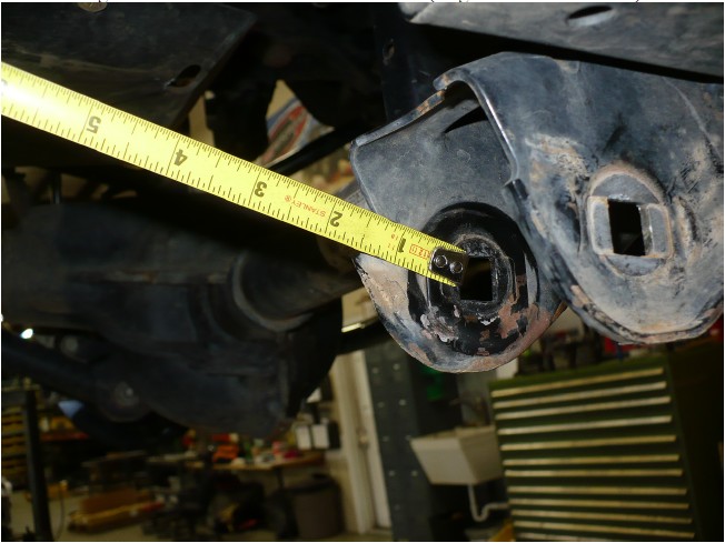
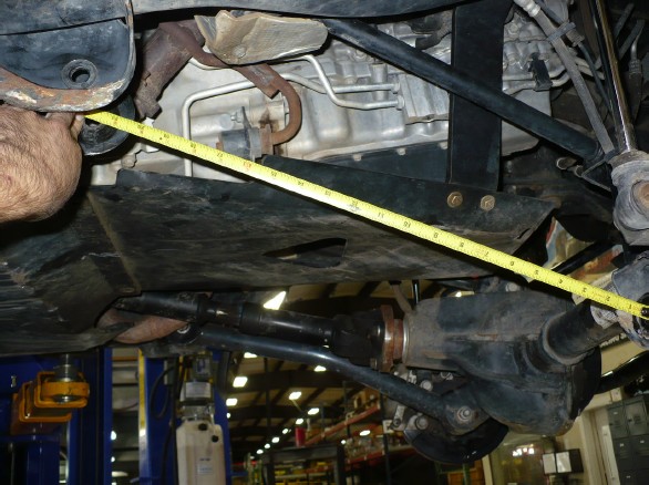
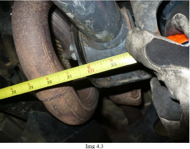
4) Next, take some reference measurements. Record several measurements. You should have 3 total measurements before cutting anything:
Front of transmission mount cross member to rear edge of control arm hole (Img. 4.1 below at 12.75”)
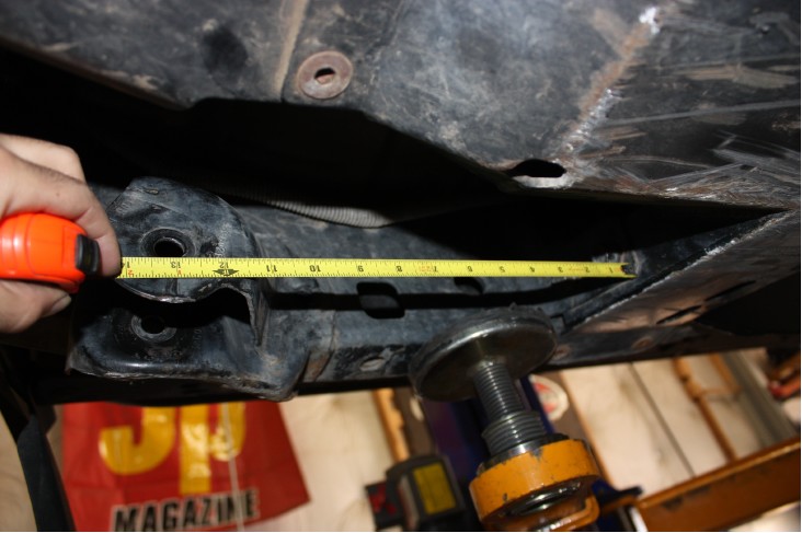
Front lower control arm mount at axle to front lower control arm mount on frame. Inner edge of holes and inner side of brackets. (Img. 4.2 below at 21.5”)
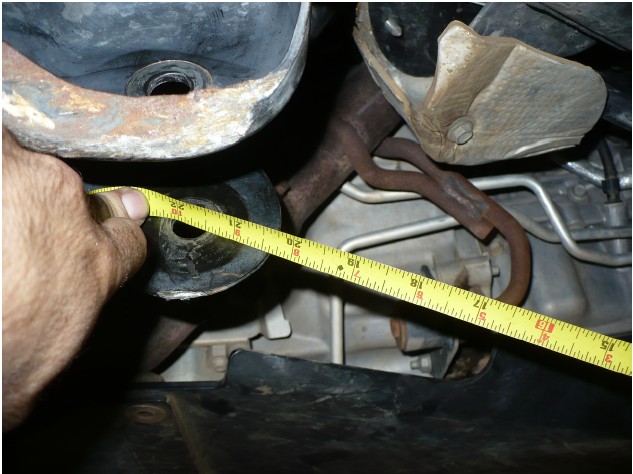
Inner edge of control arm bracket passenger side to inner edge of control arm bracket on drivers side. (Img. 4.3 below at 31.75”)
5) With these three measurements in hand, begin cutting the passenger side front lower control arm mount off the vehicle.
6) Begin by cutting the inner half of the bracket off. Completed cut should appear as shown below.
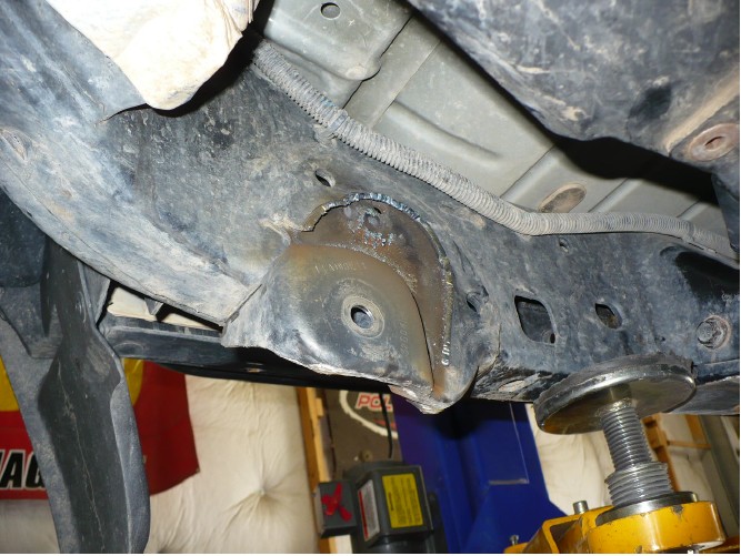
7) Next, carefully cut the outer part of the lower control arm bracket as shown below. Be careful not to cut through the frame.
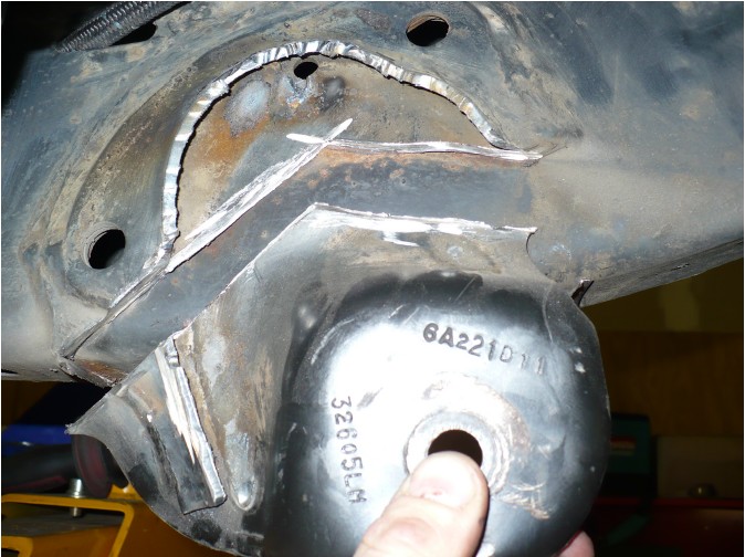
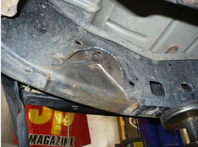
8) Use a 4-1/2” angle grinder with cut off wheel or similar cutting tool. Cut at the top of the weld as shown below. Cut through both layers of bracket, but be careful not to cut through the frame. You should end up with a deep scribe rather than a full on cut.
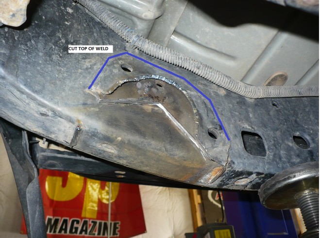
9) Once, entire weld has been cut / scribed, use a chisel to pry the remaining portion of the factory bracket away from the frame.
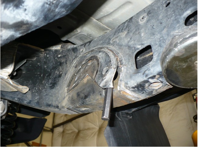
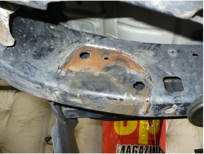
10) With bracket fully removed as shown above, grind smooth the frame.
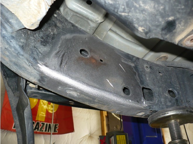
11) Test fit the bracket. The bracket should position in the same relative position as stock.
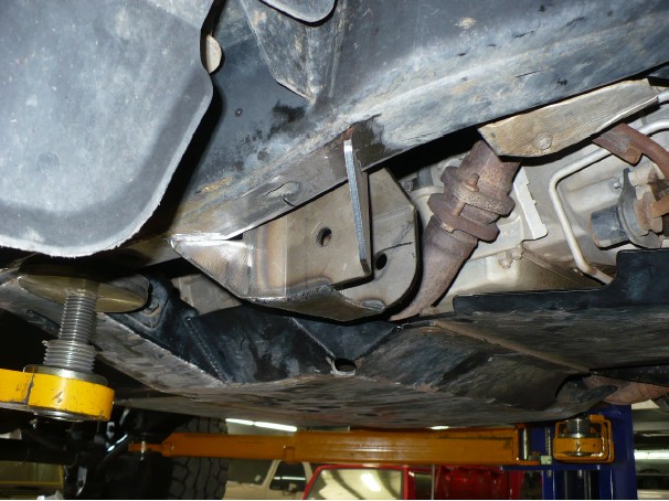
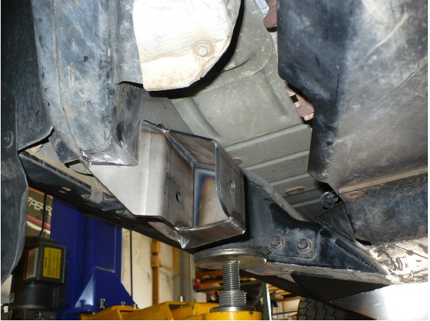
12) Use a clamp to hold the bracket into position and match the measurements taken in step 4.
13) Once satisfied with fitment, tack weld into position. Tack securely in several places.
14) At this time, reinstall control arm and take some reference measurements to ensure accurate placement.
15) Remove control arm and fully weld in position. Weld as much as desired, we recommend welding as shown below.
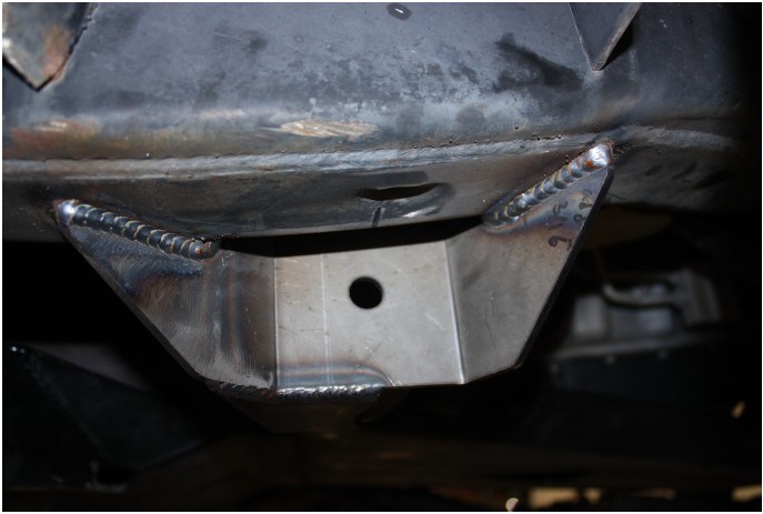
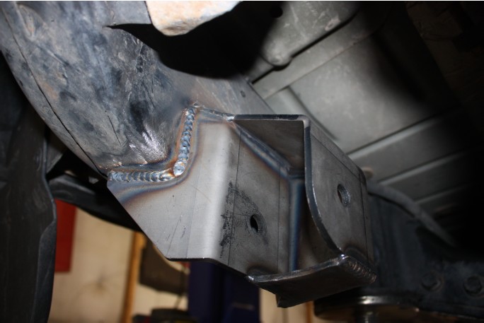
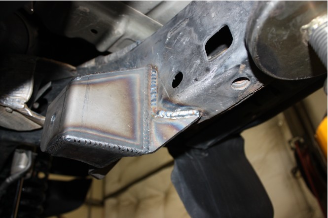
16) Allow welds to cool. Deburr welds and paint to prevent corrosion.
17) Installation on the passenger side is complete. Installation on the driver’s side follows the same procedure as the passenger side. The only difference is the exhaust makes for slightly less room to work in. Installation can be done with exhaust in place, however for easier installation, remove factory Ypipe to gain clearance.
18) If desired, remove the factory Y pipe using the factory service manual as a guide. You can also reference PPM-5017 instructions for details.
19) Follow the same procedure used on the passenger side.
20) Reinstall all lower control arm bolts and torque to mfg or stock specifications (125 ft-lbs for OEM or Synergy)
Installation is Complete

