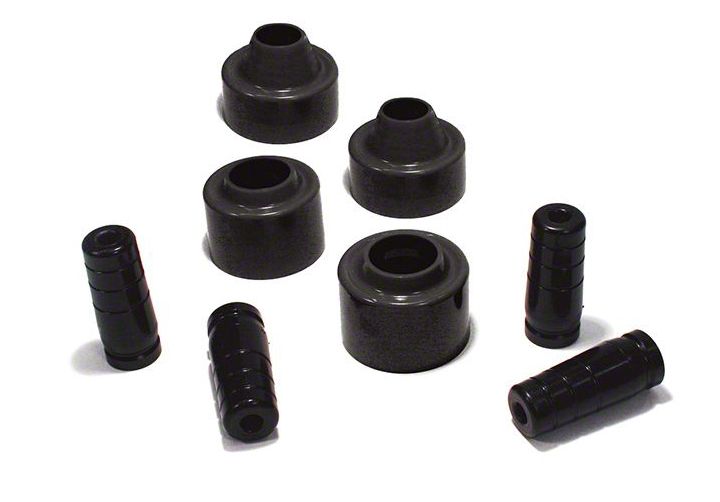

How to Install SuperLift 2 in. Coil Spacer Lift Kit w/ Bump Stops (07-18 Wrangler JK) on your Jeep Wrangler
Shop Parts in this Guide
INTRODUCTION
Installation requires a professional mechanic. Prior to beginning, inspect the vehicles steering, driveline, and brake systems, paying close attention to the suspension link arms and bushings, anti-sway bars and bushings, tie rod ends, pitman arm, ball joints and wheel bearings. Also check the steering sector-to-frame and all suspension-to-frame attaching points for stress cracks. The overall vehicle must be in excellent working condition; repair or replace all worn parts.
Read instructions several times before starting. Be sure you have all needed parts and know where they install. Read each step completely as you go.
NOTES:
• Prior to beginning the installation, check all parts and hardware in the box with the parts list below. If you find a packaging error, contact Superlift directly. Do not contact the dealer where the system was originally purchased. You will need the control number from each box when calling; this number is located at the bottom of the part number label and to the right of the bar code.
• Front end realignment is necessary.
• An arrow on diagrams indicates which direction is toward the front of the vehicle.
• A foot-pound torque reading is given in parenthesis ( ) after each appropriate fastener.
• Do not fabricate any components to gain additional suspension height.
• Paint or undercoat all exposed metal surfaces.
• Prior to attaching components, be sure all mating surfaces are free of grit, grease, undercoating, etc.
• A factory service manual should be on hand for reference.
• Use the check-off box “” found at each step to help you keep your place. Two “” denotes that one check-off box is for the driver side and one is for the passenger side. Unless otherwise noted, always start with the driver side.
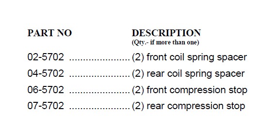
PARTS LIST … The part number is stamped into each part or printed on an adhesive label. Identify each part and place the appropriate mounting hardware with it.
INSTALLATION PROCEDURE
1) PREPARE FRONT OF VEHICLE...
Place vehicle in neutral. Raise front of vehicle with a jack and secure a jack stand beneath each frame rail, behind the trailing arms. Ease the frame down onto the stands, place transmission in low gear or “park”, and chock rear tires. Remove front tires.
Remove the front track bar bolt at the frame. Save all hardware for re-use. Loosen, but do not remove, the track bar bolt at the differential.
2) FRONT COIL SPRING SPACERS…
Position a jack so that it supports, but does not raise, the front axle.
Unbolt the lower ends of the shocks from the differential. Save all hardware for re-use.
Unbolt the anti-sway bar links from the differential. Save all hardware for re-use.
Unbolt the brake hose bracket at the frame that secures the connection between the metal line and the rubber hose. Save the hardware for re-use.
Loosen, but do not remove, the bolts securing the upper and lower link arms at both the frame and differential.
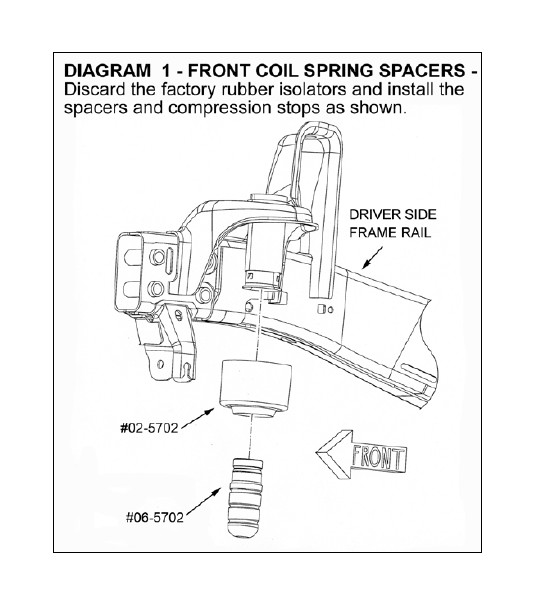
[DIAGRAM 1] Lower the axle enough to facilitate installing the #02-5702 coil spring spacers as shown. Remove and discard the factory rubber isolator. The spacer should be installed on top of the coil spring with the lip in the spacer pointing downward.
Pry out the factory compression stop from its mounting cup.
Press the #06-5702 compression stop into the factory mounting cup.
3) FRONT RE-ASSEMBLY…
Raise the axle enough to seat the coil springs against the spacers.
Re-attach the brake hose brackets to the frame using the factory hardware and tighten (250 in-lb).
Bolt the anti-sway bar links to the differential using the factory hardware, followed by the shocks. Tighten the anti-sway bar link hardware (80) and shock hardware (80).
NOTE: If the optional shock absorbers have been purchased, install them now.
4) TIRES / WHEELS…
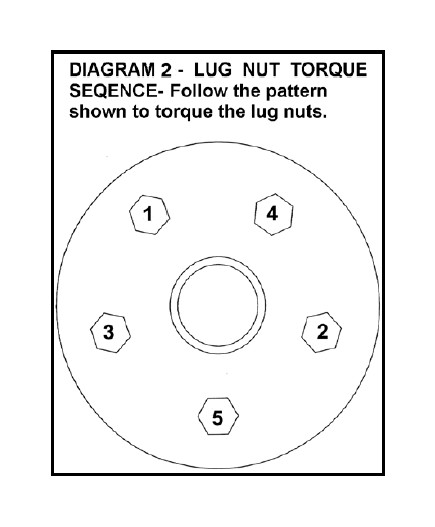
[DIAGRAM 2] Tighten the lug nuts (115) in the sequence shown. WARNING: When the tires / wheels are installed, always check for and remove any corrosion, dirt, or foreign material on the wheel mounting surface, or anything that contacts the wheel mounting surface (hub, rotor, etc.). Installing wheels without the proper metal-to-metal contact at the wheel mounting surfaces can cause the lug nuts to loosen and the wheel to come off while the vehicle is in motion.
WARNING: Retighten lug nuts at 500 miles after any wheel change, or anytime the lug nuts are loosened. Failure to do so could cause wheels to come off while vehicle is in motion.
5) PREPARE REAR OF VEHICLE…
Raise the rear of the vehicle with a jack and secure a jack stand beneath each frame rail, just ahead of the trailing arms. Ease the frame down onto the stands, place transmission in low gear or “park”, and chock front tires. Remove rear tires.
Unbolt the track bar at the frame. Save all hardware for re-use. Loosen, but do not remove, the track bar bolt at the differential.
6) REAR COIL SPRING SPACERS…
Position a jack so that it supports, but does not raise, the rear axle.
Unbolt the lower end of the shock absorbers at the axle, followed by the anti-sway bar links. Save all hardware for re-use.
Unbolt the brake hose bracket that secures the connection between the metal line and rubber hose. Save all hardware for re-use.
Loosen, but do not remove, the link arm bolts at both the axle and frame.
[DIAGRAM 3] Lower the axle enough to facilitate installing the #04-5702 coil spring spacers. Remove and discard the factory rubber isolator. The spacer should be positioned on top of the coil springs with the lip in the spacer pointing downward.
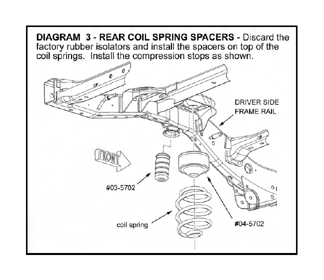
Pry out the factory compression stop from its mounting cup.
Press the #07-5702 compression stop into the factory mounting cup.
7) EMERGENCY BRAKE CABLES, TWO-DOOR MODELS…
NOTE: For four-door models, proceed to the next step.
Note that the emergency brake cables are routed above a rear frame crossmember. On each side, disconnect the emergency brake cables at the axle and re-route the cables below the crossmember. Re-attach the cables to the axle.
8) EMERGENCY BRAKE CABLES, FOUR-DOOR MODELS…
NOTE: For two-door models, proceed to the next step.
Note that the emergency brake cables are routed above a rear frame crossmember. On each side, disconnect the emergency brake cables at the axle and re-route the cables below the crossmember.
Place the factory emergency brake cable bracket on the bottom of the frame crossmember. Using the bracket as a template, mark the location for the two mounting holes to be drilled. Remove the bracket and drill at the marked locations using a 13/64” bit.
Attach the bracket to the crossmember using the supplied 1/4” x 1/2” self-tapping bolts and tighten (75 in-lb).
9) REAR RE-ASSEMBLY…
Raise the axle enough to seat the coil springs and spacers.
Re-attach the shock absorbers and anti-sway bar links at the axle using the factory hardware. Tighten the shocks (80) and anti-sway bar links (80).
NOTE: If the optional shock absorbers have been purchased, install them now.
Re-attach the brake hose bracket to the frame using the factory hardware and tighten (250 in-lb).
Install the tires and wheels following the procedure in step 4.
10) CLEARANCE CHECK...
With the vehicle still on jack stands, and the suspension “hanging” at full extension travel, cycle steering lock-to-lock and check all components for proper operation and clearances. Pay special attention to the clearance between the tires / wheels and brake hoses, wiring, etc.
Lower vehicle to the floor.
11) FINAL CLEARANCE and TORQUE CHECK...
Tighten the front and rear link arm bolts at both the axle (130) and frame (80).
Re-attach the front and rear track bars to the frame and tighten both ends of the bar (130).
With vehicle on floor, cycle steering lock-to-lock and inspect the tires / wheels, and the steering, suspension, and brake systems for proper operation, tightness, and adequate clearance.
Center the steering wheel using the adjustment found on the drag link.
Check the toe-in of the front axle. If it is out of adjustment, take the vehicle to be professionally aligned.
12) Activate four wheel drive system and verify proper engagement.
13) HEADLIGHTS...
Readjust headlights to proper setting.
14) SUPERLIFT WARNING DECAL...
Install the WARNING TO DRIVER decal on the inside of the windshield, or on the dash, within driver’s view. Refer to the “NOTICE TO DEALER AND VEHICLE OWNER” section below.
15) ALIGNMENT...
If necessary, align vehicle to factory specifications.
