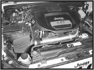

How to Install Spectre Performance Cold Air Intake - Polished (12-17 3.6L Wrangler JK) on your Jeep Wrangler
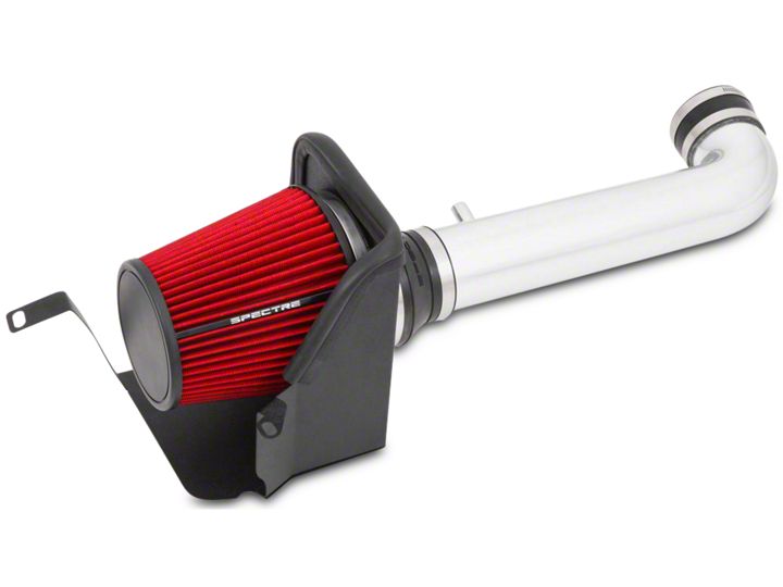
Shop Parts in this Guide
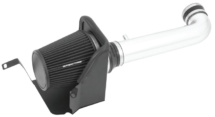
Parts List
1- Intake tube
1- Filter
1- Heat shield
1- 3 1/4”-3” Coupler
1- 4”-3” Coupler
1- Filter funnel
1- 22” Rubber seal
2- L Brackets
2- Zip ties
2- Hex bolts, M6x16
1- Hex bolts, M6x12
2- Washers, M6
1- Fender washer, M6
1- Rubber mount, M/F
1- 5/8” Hose
3- 3” Hose clamps
1- 4” Hose clamp
1- 5/8” Hose clamp
1- 1/2”ID grommet
Step 1: Safety first! Before you begin the installation, make sure that the vehicle is in park (or neutral for a manual transmission) with the parking brake set. Disconnect the negative battery terminal and verify that all components that are listed are present. Note: This kit was designed and tested on a stock engine without any custom tuning done to the engine computer. Removing the battery cable may erase the programmed radio stations. The anti-theft code will need to be entered into some radios after the battery cable is connected. The anti-theft code can typically be found in the owner’s manual or at your local dealership.
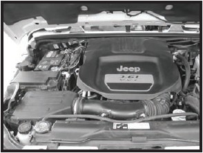
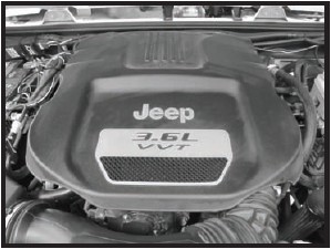
Step 2: Remove the engine cover that is attached by lifting the cover up and off.
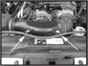
Step 3: Unclip the coolant vent line from the air intake tube and remove the two screws that secure the tube to the fan shroud.
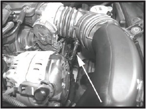
Step 4: Disconnect the Inlet Air Temperature (IAT) sensor connector.
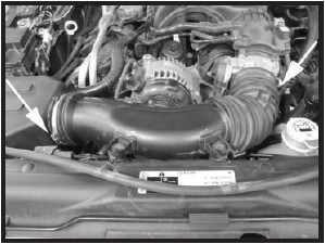
Step 5: Loosen the clamp at the throttle body and the air box. Remove the factory intake tube from the vehicle.
Step 6: Disconnect the crank case hose from the crank case tube.
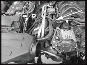
Step 7: Remove the factory air box from the vehicle by pulling the air box firmly upward.
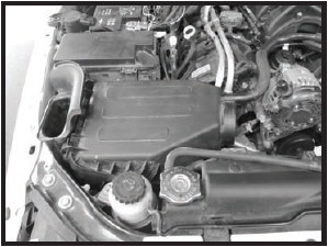
Step 8: Install the rubber bulb seal.
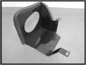
Step 9: Remove the bolt that holds the lower air box tray to the inner fender.
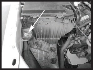
Step 10: Install the rubber mount in place of the bolt removed on Step 9.
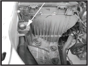
Step 11: Remove the bolt that secures the power steering reservoir to the vehicle. This bolt will be re installed with the new heat shield.
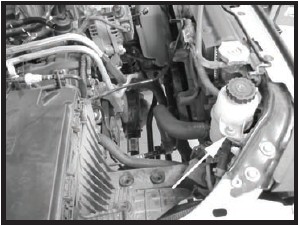
Step 12: Install the heat shield into the vehicle as shown. Re install the bolt removed from Step 11 and the supplied hardware for the other bolt hole location.
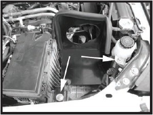
Step 13: Install the two “L” brackets onto the fan shroud making sure you use slotted hole for the mounting location. Once the brackets are mounted, using the supplied zip ties, insert the mounting peg thru the round hole on the brackets, securely fasten the coolant hose in place. Trim the excess if desired.
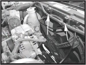
Step 14: Turn the IAT sensor counterclockwise and remove it from the factory intake tube. Remove the O-ring from the sensor.
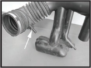
Step 15: Install the supplied grommet into the intake tube and install IAT sensor into the grommet.
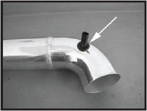
Step 16: Install the couplers onto the end of the tube and fasten it securely, leaving the other clamps loose at this time.
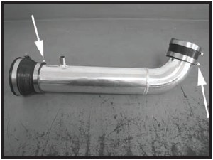
Step 17: Install the intake tube onto the throttle body with the tube rotated in the upward position allowing yourself access to reconnect the IAT sensor. Reconnect the IAT at this time.
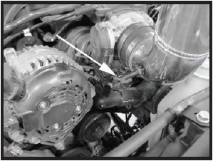
Step 18: Rotate the intake tube and line up the coupler roughly with the hole in the heat shield. Install the filter funnel in the heat shield and onto the reducer coupler. Once the tube is in the desired location, tighten all the clamps. The velocity adapter may be rotated slightly once the filter is installed in the vehicle.
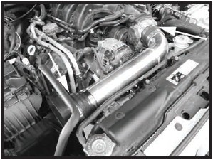
Step 19: Install the new crank case vent hose onto the crank case vent tube and intake tube. Install the clamp on the intake tube end of the hose.
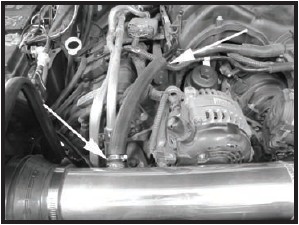
Step 20: Install the filter on the velocity stack adapter and fasten it securely. If required rotate the velocity adapter so the filter will fit without any fitment issues.
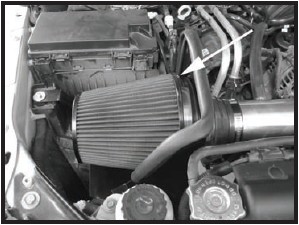
Step 21: Reinstall the engine cover. Make sure that all clamps and hardware are fully tightened. Reconnect the battery cable, start the vehicle and let it warm up. Shut off and inspect the installation once more for any loose clamps, wires, or hardware. Test drive & enjoy! Your installation is now complete. Periodically check all clamps and brackets.
