
How to Install SkyJacker 6 In. Bent Long Arm, Suspension System w/ Nitro Shocks on your Wrangler
Tools Required
- * Safety Glasses
- * Metric / Standard Wrenches & Sockets
- * Allen Wrenches
- * drill & Assorted drill Bits
- * Grinder / Cut off Wheel
- * Pipe Wrench
- * Floor Jack
- * Jack Stands
- * Measuring Tape
- * Torque Wrench
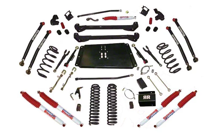
Shop Parts in this Guide
Make sure you park the vehicle on a level concrete or asphalt surface. Many times a vehicle is not level (side-to-side) from the factory & is usually not noticed until a lift kit has been installed, which makes the difference more visible. Using a measuring tape, measure the front & rear (both sides) from the ground up to the center of the fender opening above the axle. Record this information below for future reference.
Driver Side Front: ___________________ Passenger Side Front:_________________
Driver Side Rear: ___________________ Passenger Side Rear:_________________
IMPORTANT NOTES:
• This lift is determined from the amount of lift to the front of the vehicle, while only lifting the rear to a position level with the front.
• If larger tires (10% more than the stock diameter) are installed, speedometer recalibration will be necessary. Contact your local Jeep dealer or an authorized dealer for details.
• After installation a qualified alignment facility is required to align the vehicle to factory
specifications.
• 6-Speed transmission models may require additional modifications, contact Skyjacker @ 318-388-0816 for additional information.
• Exhaust modifications may be necessary.
• A slip yoke eliminator kit (Part # RR231) & a rear C.V. drive shaft are required.
• Rubicon models require a C.V. yoke (Part # CVR680) & a replacement C.V. drive shaft.
• 2003-2006 models with an automatic transmission must remove the front transmission skid plate for driveshaft clearance.
Pre-Installation Tips:
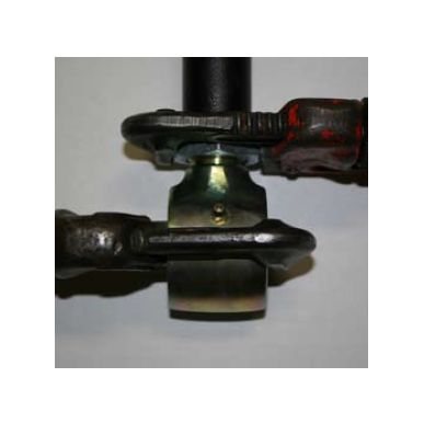
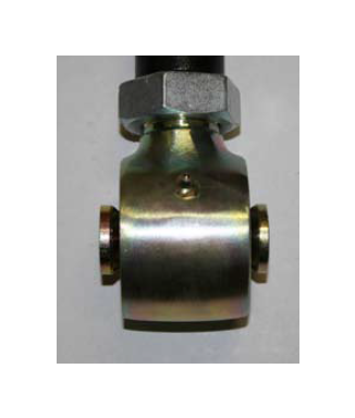
Now you are ready to "set" the length of the new Rock Ready™ link assemblies. It is very important to position the swivel ball socket so that the bushings are exactly centered. Measure the length of the link assembly between the center of the eyelet & the rod end. Rotate the rod end as needed, being sure to keep the rod end square with the eyelet end until the link assembly measures:
6" Measurements
Lower Front should be set @ 30 1/8"
Lower Rear should be set @ 29 1/8"
Upper Front should be set @ 15"
Upper Rear should be set @ 14 1/4"
These are pre-alignment measurements only. Final measurements are to be set by a qualified alignment facility.
On the rod end, rotate the jam nut against the steel tubing. Hold the rod end in place with a pipe wrench & use another pipe wrench on the jam nut to completely tighten.
NOTE: The jam nut must be tightened against the steel tubing before installation.
Front Installation:
1. Secure & properly block the tires of the vehicle on a level concrete or asphalt surface.
2. Raise the front of the vehicle & support the vehicle with jack stands.
3. Remove the front tires, front shocks, steering stabilizer, & track bar.
4. Remove the draglink from the pitman arm & install the new Skyjacker pitman arm at this time.
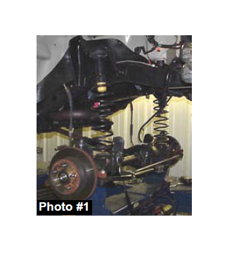
5. Remove the sway bar end links & brake calipers from the OEM mounts. (See Photo # 1)
6. Lower the front differential & remove the front coil springs.
7. Remove the OEM bump stop by pulling back & forth with pliers & install the new Skyjacker poly bump stops.
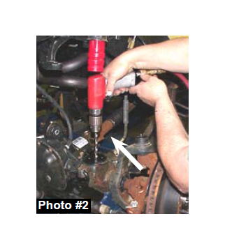
8. Drill a 3/8" hole in the indent of the lower coil seat & install the new Skyjacker (round) polymer bump stop spacer. (See Photo # 2)
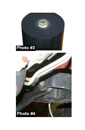
9. Tighten the 3/8” bolt until the top of the washer is flush with the top of the new Skyjacker bump stop spacer. (See Photo # 3)
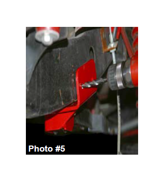
10. Disconnect the upper front control arm from the frame & axle. Note: Only disconnect one arm at a time so that the axle does not roll. (See Photo # 4)
Important Note:
Exhaust modifications may be necessary to allow for articulation & clearance of the new Skyjacker drop down bracket. On some models, the cross over pipe will need to be shortened so that it does not run under the control arm & new bracket.
11. Install the new Skyjacker upper arm relocation bracket & attach it to the OEM control arm position using the OEM hardware.
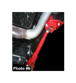
12. Attach the new Skyjacker upper control arm to the new Skyjacker bracket using the 10mm x 80mm bolt supplied. Attach the new Skyjacker upper control arm to the axle using the OEM hardware. There are four more mounting locations that attach this bracket to the frame. Two on the outside & two on the bottom. With the bracket sitting flush on the frame, drill these locations using a 9/32” drill bit. Once drilled, install the 3/8" x 1” thread cutter bolts in these locations. (See Photo # 5 & # 6)
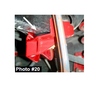
Note: Some models may have a slight gap between the bottom of the new Skyjacker bracket & the frame on the driver side. If this occurs, this gap can be taken up using the 1/4” plastic shim provided. Place the shim between the bracket & the frame. Using a C-Clamp, pull the bracket & shim flush to the frame. (See Arrow in Photo # 20) Drill through the plastic shim & the frame. Mount using the 3/8" x 1 1/4” thread cutter bolts provided.
13. Remove the front lower control arms. Using care, grind off the OEM lower control arm mounts & paint the exposed surface. (See Photo # 7)
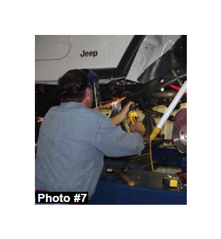
14. Place a jack under the transmission skid plate. Remove the mounting hardware & lower the skid plate two inches.
15. Place the new Skyjacker left & right sub frames between the bottom of the frame & install the new Skyjacker high clearance skid plate using the instructions provided. Fasten using the 1/2" x 3” flat socket bolts on 97-02 models & use the 12mm x 80mm bolts on the 03-06 models. (See Photo # 8) Note: On some models it may be necessary to grind down the OEM rear step bar nut insert on the outside of the frame. This will allow for the subframe rail to mount flush.
16. Install the new Skyjacker transfer case shifter bracket (Part # JSRB231A) using the instructions provided.

Note: Skyjacker sub frames are designed to work on 1997-2006 Jeep TJ’s. Therefore, each sub frame will have multiple mounting holes.
• 1997-2002 models use mounting holes 1,3, & 5.
• 2003-2006 models use holes 2 & 4. See I-TJ68SP instruction for the 3rd mounting bolt & skid plate modifications.

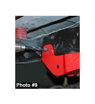
17. With the new Skyjacker sub frame attached with the lower bolts, drill the outer mounting locations using a 1/2” drill bit. Drill completely through the frame & the mounting tab located on the back side of the sub frame. (See Photo # 9) Once Drilled, install the 1/2" x 4” fine thread bolt, washers, & nuts.
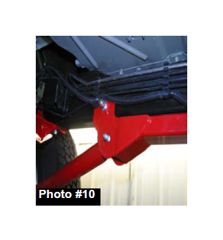
18. The new Skyjacker lower control arms mount to the OEM lower location at the differential & to the new position of the Skyjacker sub frame. Insert two large stepped spacers into the rod end & two bushings & sleeve into the eyelet end of the new Skyjacker lower control arms & fasten using the OEM hardware. Install the rod end to the axle mount & the bushing end to the frame mount. (See Photo # 10)
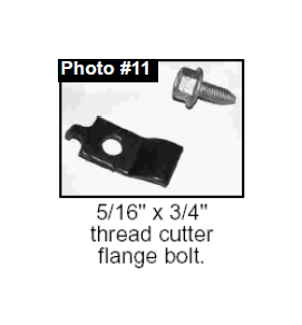
19. Lower the front differential & install the new Skyjacker coil springs placing the top of the coil spring over the upper bump stop mount first. Provided with the coil springs is the clip & hardware to fasten the passenger front coil spring like the driver’s side. (See Photo # 11) The OEM manufacturer provides the hole in the left lower coil spring mount for you to fasten the coil spring securely to its seat. Install it the same as on the driver side.
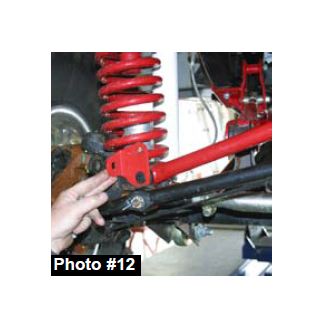
20. Install the new Skyjacker adjustable track bar by first greasing & installing the two poly bushings & sleeve. Insert the poly end into the OEM steering stabilizer location on the passenger side of the axle, not the OEM track bar location. Install the new Skyjacker steering stabilizer mounting bracket with the tab over the OEM sway bar end link stud using the OEM nut. Use the 1/2" x 2 1/2" flat socket head bolt & stover nut to bolt the new Skyjacker bracket to the track bar. (See Photo # 12) Note: In extreme situations (Depending on pinion angle & caster settings), the drag link may contact this bracket when turning. This bracket can be slightly ground for additional clearance, if needed.
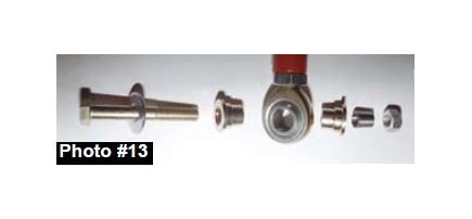
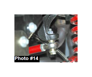
21. Install the frame end of the new Skyjacker track bar by following the hardware pictured. (See Photos # 13 & 14) Being sure to keep the rod end square (parallel) with the frame mount. Note: Be sure no more than 1/2" of threads are extended from the bar (including the jam nut). Hold the rod end in place with a crescent wrench & tighten using a pipe wrench or crescent wrench on the jam nut.
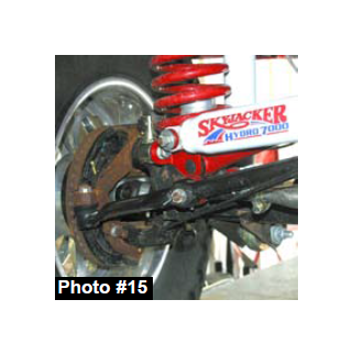
22. Install the steering stabilizer mounting stud in the hole of the drag link & upper mounting hole on the new Skyjacker track bar bracket. Install the provided 5/8 hourglass bushings into the new Skyjacker steering stabilizer & attach to the new Skyjacker studs. (See Photo # 15)
23. Install the front brake lines using the instructions provided with the brake line kit.
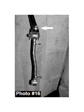
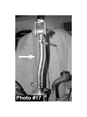
24. The new Skyjacker end link mounting bracket should be mounted to the bottom of the sway bar with the bolt pointing up through the sway bar & with the nut & washer applied on top. (See Photo # 16) Apply grease to the polyurethane bushings & insert them into the end link eyes along with the sleeve. The top 1/2" x 2 1/2" bolt connecting the bracket to the end link must be installed with the nut to the outside of the vehicle to provide adequate clearance to the frame. Install the new Skyjacker double disconnect end links on the inboard side of the axle bracket, being sure that the offset is turned inward.(See Photo # 17)
25. Install the front tires & lower the vehicle to the ground.
Rear Installation:
1. Raise the rear of the vehicle & support the vehicle with jack stands.
2. Remove the rear tires & shock absorbers.
3. Disconnect the rear track bar from the differential & remove the sway bar end links.
4. Lower the differential & remove the rear coil springs.
5. Drill a 3/8" hole into the center of the rear lower spring seat.
6. Remove the upper bump stop by pulling back & forth with pliers. Replace with the new Skyjacker poly bump stop.
7. Install the new Skyjacker rear coil springs.
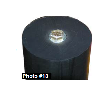
8. Slide the new Skyjacker polymer bump stop spacer between the wraps in the coil spring. Attach the bump stop spacer to the previously drilled hole using the 3/8" x 4" fine thread bolts, washers, & nut. Tighten the 3/8” bolt until the top of the washer is flush with the top of the bump stop spacer. (See Photo # 18)
9. Place the new Skyjacker track bar relocating bracket over the OEM track bar mount at the differential. Place the new 12mm x 70mm bolt through the OEM track bar location. Use the supplied spacer to fill the space where the OEM track bar was located. Apply the lock nut & tighten.
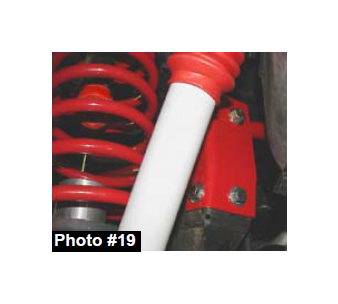
10. Drill a 1/2" hole through the hole in the driver’s side of the new Skyjacker track bar bracket. Install the 1/2" x 1 1/4" bolt with washers on each side through the newly drilled hole & tighten with the self locking nut. Install the 5/16" x 1" fine thread bolt, washers, & nut into the forward hole of the new bracket. (See Photo # 19)
11. Install the new Skyjacker adjustable rear track bar using the instructions provided. Be sure to install both the upper & lower bolts from the rear forward.
12. Remove the upper control arms, freeing the rear brake line, emergency brake cables, & rear sway bar end links.
13. Install the new Skyjacker upper control arm relocating brackets. These brackets & control arms will install the same as the front. While still installing one at a time so that the axle does not roll.
Note: Some models may have a slight gap between the bottom of the new Skyjacker bracket & the frame on driver side. If this occurs, this gap can be taken up using the 1/4” plastic shim provided. Place the shim between the bracket & frame. Using a C-Clamp, pull the bracket & shim flush to the frame. (See Arrow in Photo # 20) Drill through the plastic shim & through the frame. Mount using the 3/8" x 1 1/4” thread cutter bolts provided.
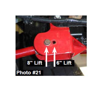
Note: The rear upper link brackets feature two mounting locations for the upper arms. When installing a Skyjacker 6” lift, use the forward hole in the bracket. (See Photo # 21)
14. Insert two step spacers into the rod end & two bushings & sleeve into the eyelet end of the new Skyjacker upper control arm. Install the new Skyjacker upper control arm with the rod end to the axle mount & the bushing end to the frame mount.
15. If the vehicle is equipped with an optional upper control arm eccentric cam bolt, they must be reused. Attach the OEM emergency brake bracket to the new Skyjacker upper control arm bracket using the plastic-tie provided.
16. Assemble the new Skyjacker rear sway bar end links by applying grease to the poly bushings & inserting them into each eye along with a sleeve. Install using OEM hardware.
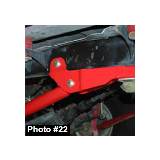
17. Remove the lower control arms & rear lower control arm mounts at the frame. Repeat the process from the front lower control arm mount. Clean & paint the exposed surfaces. The new Skyjacker rear lower control arms mount to the OEM lower location at the differential & to the new position of the sub frame. Insert two step spacers into the rod end & two bushings & sleeve into the eyelet end of the new Skyjacker lower control arm. Install the new Skyjacker lower control arm with the rod end to the axle mount & the bushing end to the frame mount. Fasten using the OEM hardware. (See Photo # 22)
18. Install the rear brake line, rear coil springs, & shocks.
19. Reinstall the rear tires & lower the vehicle to the ground.
FINAL NOTES:
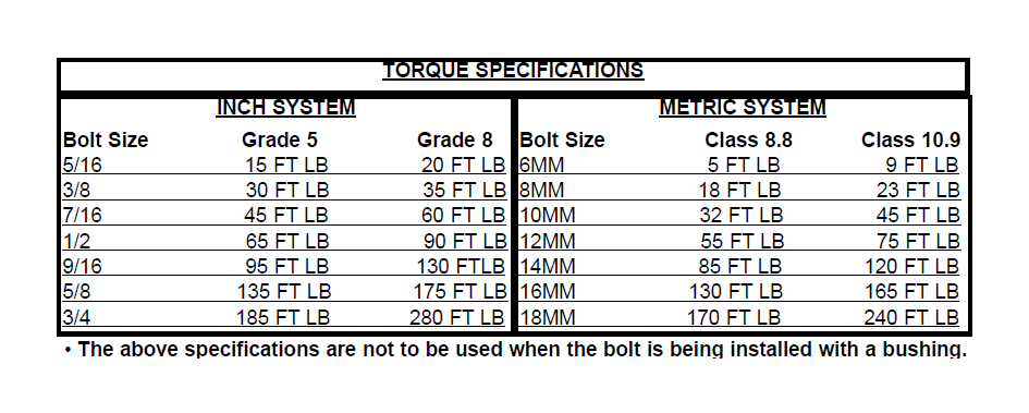
• After the installation is complete, double check that all nuts & bolts are tight. Refer to the following chart again for the proper torque specifications. (Do not retighten the nuts & bolts where thread lock compound was used.)
• With the vehicle placed on the ground, cycle the steering lock to lock & inspect the steering, suspension, brake lines, front & rear drivelines, fuel lines, & wiring harnesses for proper operation, tightness, & adequate clearance.
• Have the headlights readjusted to the proper settings.
• Have a qualified alignment center realign the front end to the factory specifications.
• Retorque all the bolts after the first 100 miles.
Part # TJ676XPN
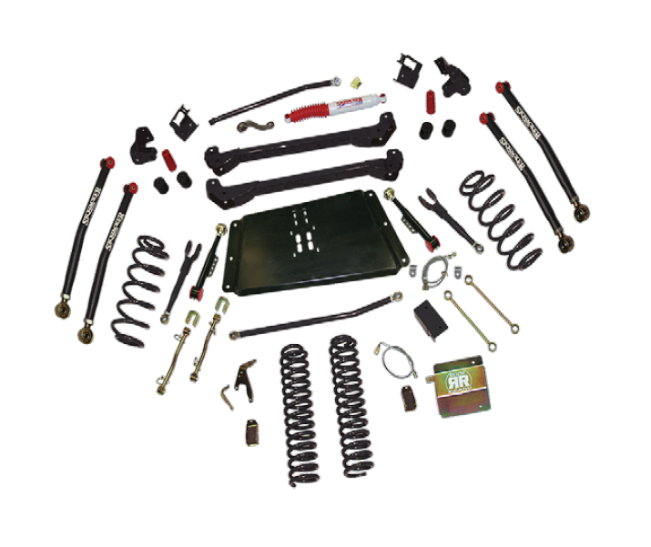
Note: 03-06 models will require modification to the OEM skid plate in order to install the Skyjacker sub frame.
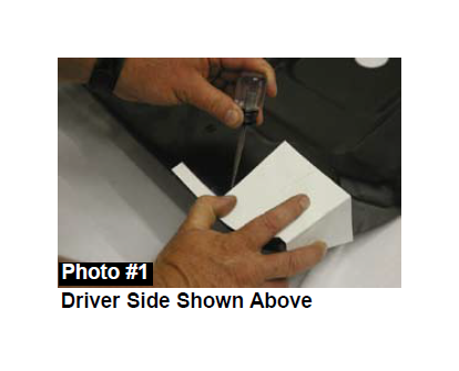
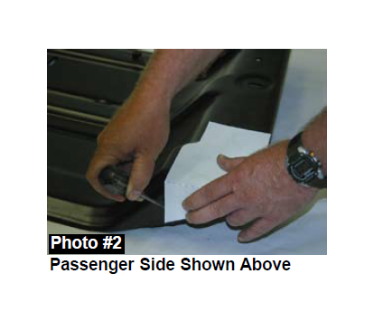
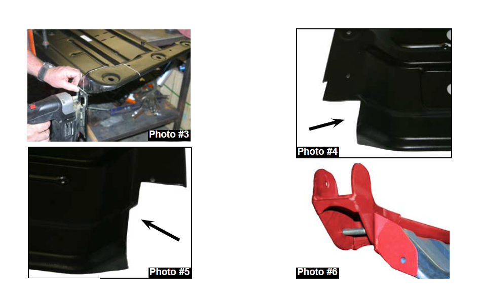
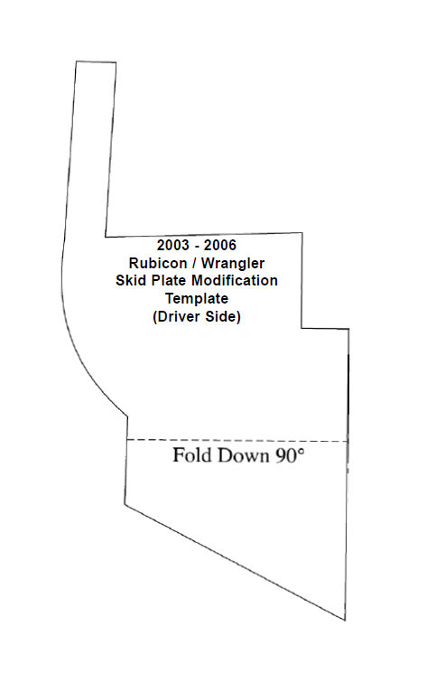
1. With the skid plate removed, use the supplied templates to scribe & cut the rear of the OEM transfer case skid plate. (See Photo # 1, # 2, & # 3)
2. Photo # 4 shows the portion removed from the driver side. Photo # 5 shows the portion removed from the passenger side.
3. With the transfer case skid plate modified, locate the new Skyjacker rear mounting brackets. Mount the new bracket to the new control arm mounting point on the sub frame. Mount using the OEM lower control arm bolt. Install the bracket so that it is flush against the sub frame & the back of the skid plate. (See Photo # 6)
4. Once installed, mark & drill the new mounting point on the skid plate using a 3/8" drill bit. Install & tighten the new 3/8" x 1 1/4” bolt & hardware at this time.
Refer back to lift kit instructions at this time.
