

How to Install Rough Country 2 in. Black Series LED Cube Lights w/ Windshield Mounting Brackets (2018 Jeep Wrangler JL) on your Jeep Wrangler
Installation Time
60 minutes
Tools Required
- Hex (Allen) Key (4mm)
- Ratchet (1/8”)
- Torx (40 and 45mm, Included with the JL)
- Wrench (10mm, optional)
- Towel (To protect the paint)
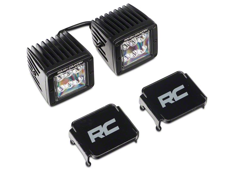
Shop Parts in this Guide
Note: Park the vehicle on a safe and leveled surface and wear protection gear.
Installation Instructions:
1. With the 40mm Torx bit and the ratchet that came with the JL, remove the cowl cover.
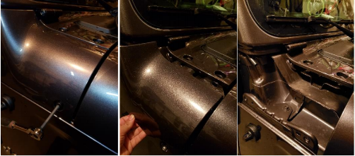
2. Put the towel on top of the cowl and place the light on top of it. Tuck the cable near the windshield hinge and leave the connector reachable from the hood.
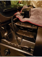
3. Slide in the cowl cover. Using the 45mm Torx included with the JL loose the bolt in the windshield hinge. Do not remove this screw completely. Leave only enough space to slide in the light mounting bracket.
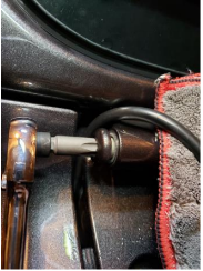
4. Place the rubber spacer provided in place of the Torx screw that came with the JL. Then slide in the bracket in the windshield hinge and secure using the provided bolt.
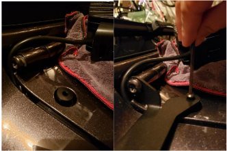
5. Using the 45mm Torx bit and the ratchet, tight the screw in the windshield hinge.
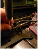
6. Now secure the light to the bracket using the provided hardware. Tight with a 14mm wrench.
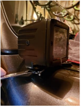
7. Every build is unique and there are many ways to run the wiring and install the on/off switch. You should consider among other things the other electronics in your build (current and future) and then plan how to route the wires.
Some guiding principles should be followed as follows:
a. Plan ahead where the on/off switch will be mounted.
b. Route the harness to the mounting location but don’t secure (e.g. zip-tie) until all connections have been performed.
c. Avoid sharp edges, abrasive surfaces and heat sources.
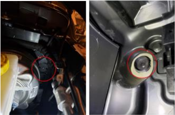
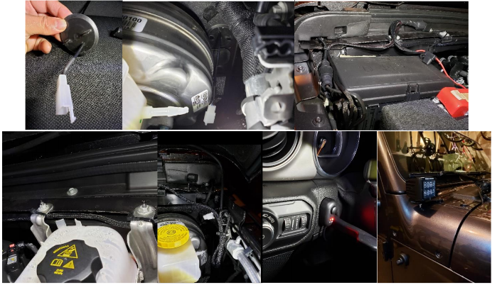
8. There are two firewalls on the JL. The easier to access is the one the driver’s side (shown below). The one on the passenger’s side is more difficult to access as it sits in about the same area but is covered by the back-up battery. The first pic below shows the firewall in the driver’s side from the engine bay and the second picture from the inside of the vehicle.
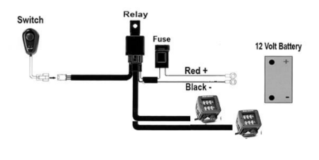
9. See the wiring diagram below. Note that the black cable can be connected to the negative terminal of the battery (as shown below) or to a suitable ground.
10. Below are some pics of a sample wiring.
Installation Instructions Written by ExtremeTerrain Customer Duamel Santiago 12/2/2018

