FREE 1 to 3-Day Delivery on Orders $119+ Details

How to Install LoD Offroad Sliding Roof Rack on your Wrangler
Please read through the instructions before beginning any part of the installation process.
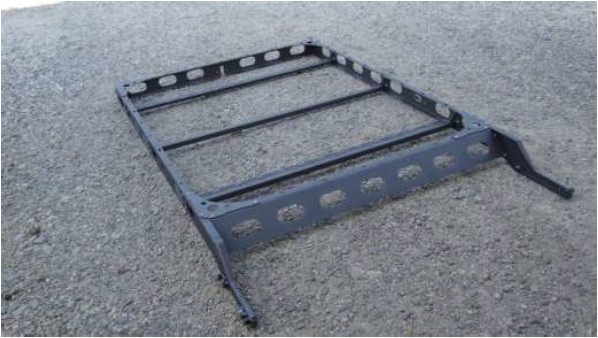
1) Begin by laying out the parts to the main rack assembly first.
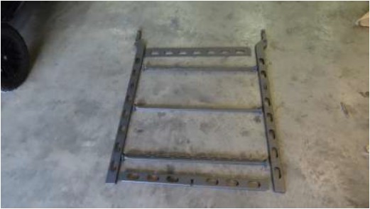
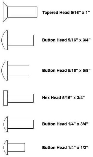
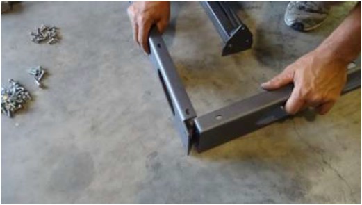
2) Start by bolting the rear corners together which will hold the two sides together and standing in the upright position. Use (2) two button head 5/16”x 3/4“ bolts in each corner.
3) Place the floor support struts between the two sides. Two (2) bars will have a slotted bracket across them and one (1) will not. Place the two bars with the brackets on each end, meaning one at the front and one at the rear, with the slotted part toward the center of the rack. Use (6) six button head 5/16”x 3/4“ bolts in each square tube strut.
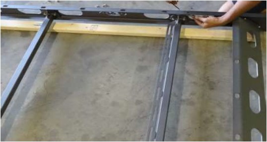
4) The center bar will not have any slotted tabs on it. It is only used to support the floor system of the rack.
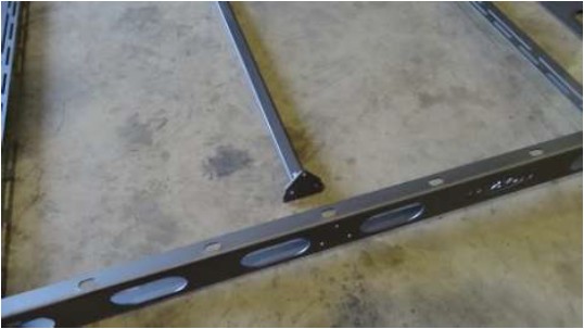
5) Bolt the front cross-member in across the front of the rack system. Use (4) four button head 5/16”x 3/4“ bolts for this. Place the lower bolt so that the nut will be on the top side. The bolt will be sticking upward.
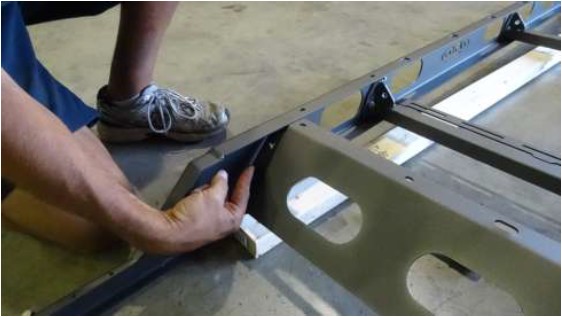
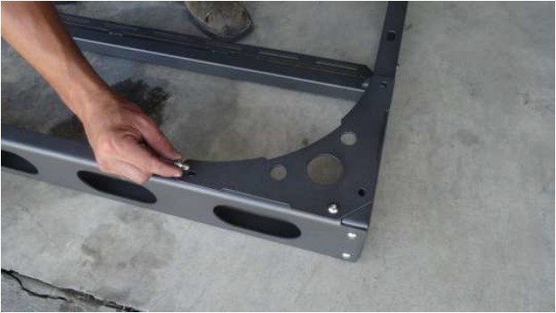
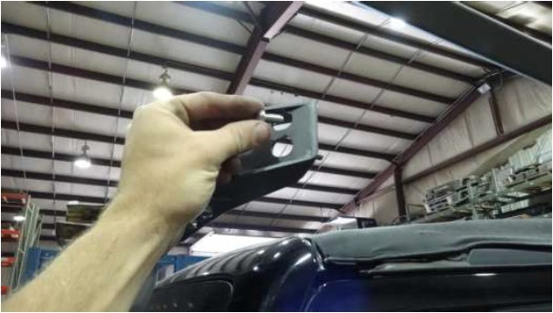
6) Next locate the (4) four plates that bolt to the top side of the rack that will hold the rack square.
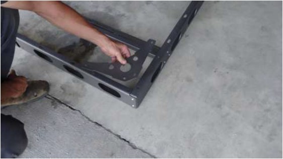
7) The brackets require (4) four button head 5/16”x 3/4“ bolts each.
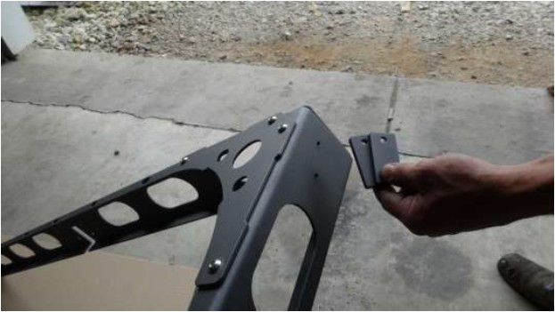
8) Next place three 1/4" plates together. These will be used to space the latching mechanism out from the rack itself. (Note: These are important and are required for the latch so that it properly latches into the closed position.)
9) Using two (2) button head 1/4"x 3/4” button head bolts secure the latch to each side of the rack.
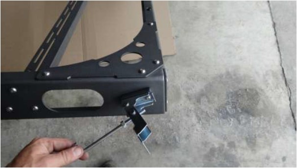
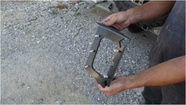
10) This completes the assembly of the sliding portion of the rack system.
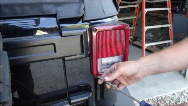
11) Remove the tail lights on both sides. You will reuse the factory screws. (Note: You only need to remove the two (2) inside screws to remove the tail lights. The outside screws only hold plastic trim to the light itself.)
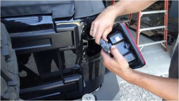
12) Unplug the harness from the lights. The plug is released by pressing the tab and pulling the plug apart. (Note: When removing the plug it helps to wiggle the plug as you pull.)
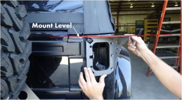
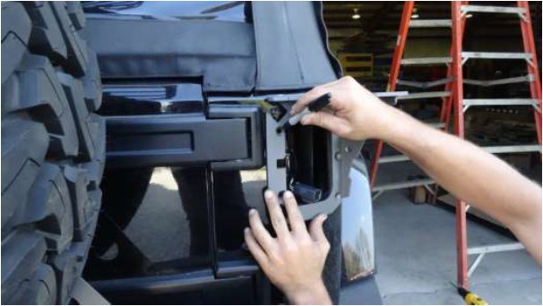
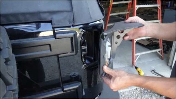
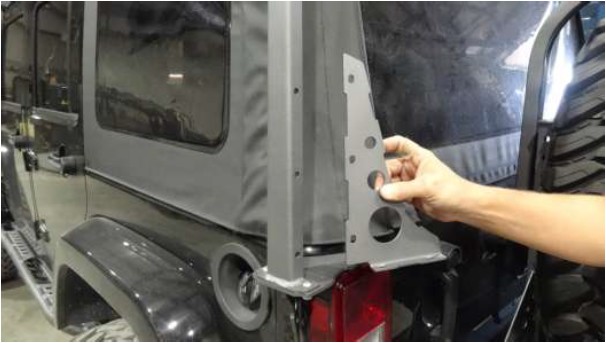
13) With the tail lights removed begin by placing the rear mounts up to the existing tail light openings. (Note: It is important to spend some time properly aligning these mounts. They need to be located with the top plate level across the back. The opening in the mount and the opening of the light hole should be carefully aligned.)
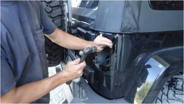
14) Carefully mark the holes on the rear mounts. Use a marker or something that can easily be seen. (Note: Placing a piece of masking tape on the body first is a good way to make the holes easy to mark.)
15) Before drilling use a center punch to mark the center of each hole. This will help ensure that the drill bit will not move after drilling begins. (Note: Gently mark the location of these holes. Remember you are marking light gauge sheet metal which will easily deform. Do not hit the punch hard for marking these.)
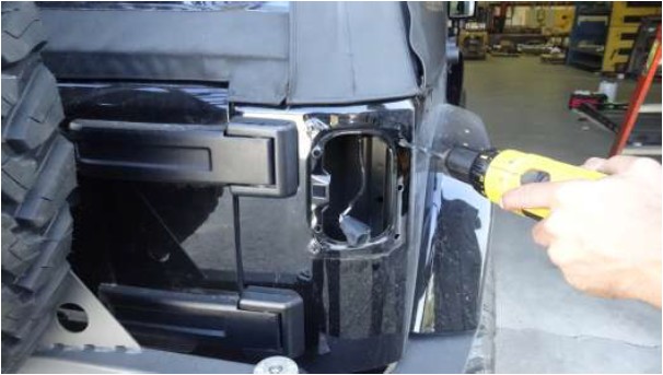
16) When drilling holes begin by using a small drill bit (roughly 3/16”). This is called a pilot hole. After drilling the pilot holes use a 3/8” drill bit to re-drill the holes to their final size.

17) After all of the holes have been drilled with the 3/8” bit it is a good idea to coat the edge of the holes you drill with a coat of paint. Use a small brush or paint stick to do this. This will ensure the edge of the drilled holes does not rust.
18) Place the rubber gaskets that are provided on the back side of the body mounts. The gasket shape will match the shape of the mount.
19) Place the five (5) tapered head 5/16”x1” bolts into the mounts and through the rubber as shown in the picture.
20) With the bolts pushed through the mounts put the mount onto the body.
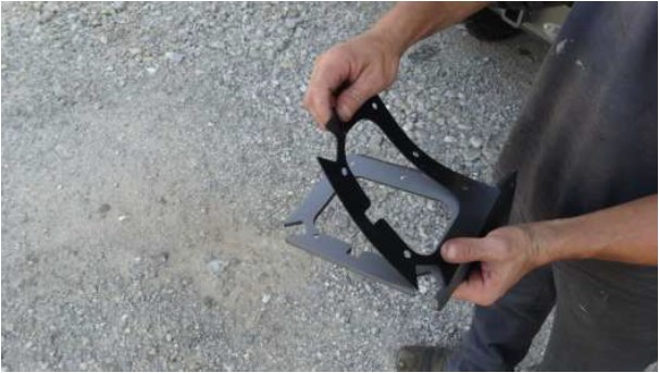
21) Locate the backing plate and orient it so that the holes line up with the bolts.
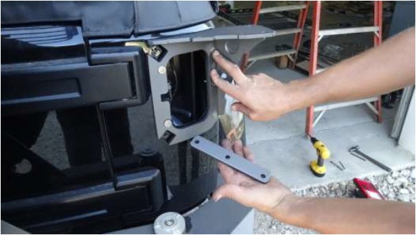
22) Place the plate inside the tail light opening and onto the bolts. (Note: This plate is important and should never be left out. The plate distributes the pressure of the nuts along the whole side of the opening.)
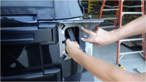
23) Tighten all five (5) bolts for each of these mounts.
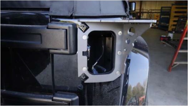
24) The light can now be re-inserted into the opening. Be sure to plug the light back in before screwing light back on.
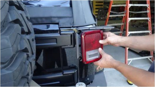
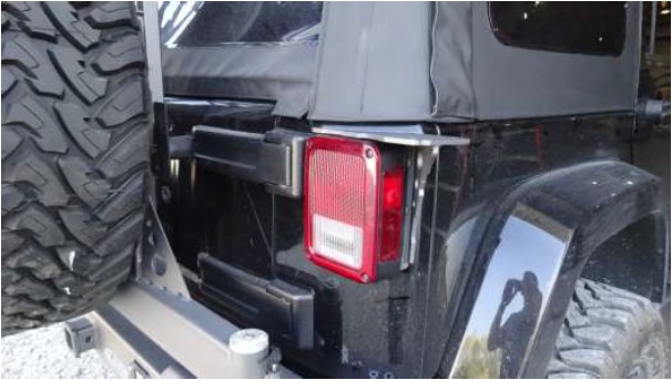
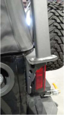
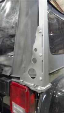
25) The finished rear mount will look like this. (The holes drilled into the body would be completely hidden behind the light if the rack was ever removed.)
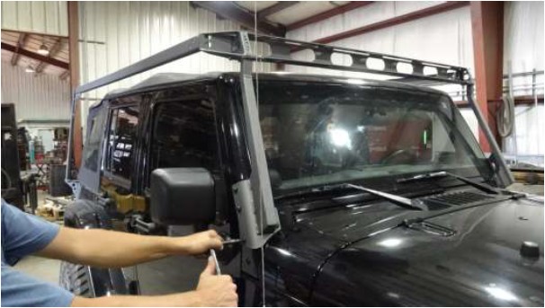
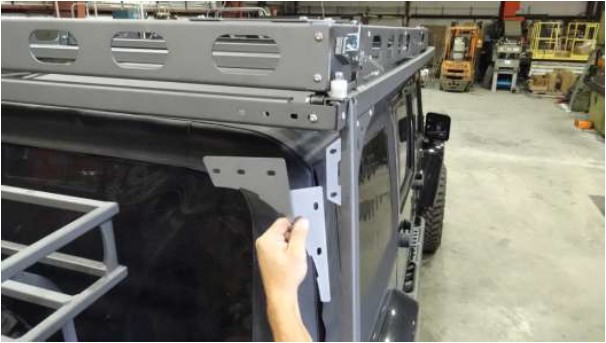
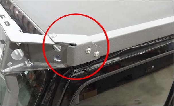
26) Remove the four (4) bolts that are circled in red from the window brackets on each side.
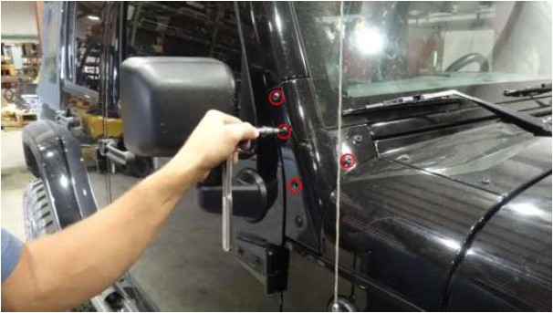
27) Locate the mounts for the front of the rack that bolt to these locations. Place the rubber gaskets onto the mounts so that they will be between the mount and the window bracket.
28) Place bracket up to the window mounts.
29) Place the original bolts back into the brackets. Occasionally a longer bolt may be required for mounting. Leave these bolts loose for now.
30) Go back to the rear mounts from earlier and place the upright mounts onto the top of the tail light mounts.
31) Put two (2) button head 5/16”x 3/4“ bolts into each side. Do not tighten these bolts either. Leaving all bolts loose at this point will make the alignment of other parts later possible.
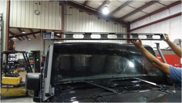
32) Place front cross-member up across the two front windshield mounts. This may take two people to ensure the part does not fall into the windshield.
33) Place three (3) button head 5/16”x 3/4“ bolts into the mounts. Place the bolts down through the mount. Leave these bolts loose as well. At this point everything should still be mounted loosely so that all parts are easily moveable.
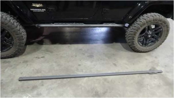
34) Lay out the main rails for the rack on each side. The single slotted tab will be placed to the top side of the rail on each side. This will determine which side is which.
35) Put two (2) button head 5/16”x 3/4“ bolts into the mount above the windshield. The rail will mount to these bolts.
36) Carefully place the main rail up onto the bolts placed through the front crossmember. Put the nuts onto these bolts but do not tighten them either.
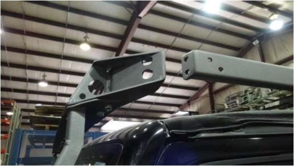
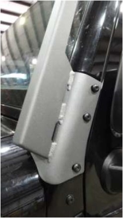
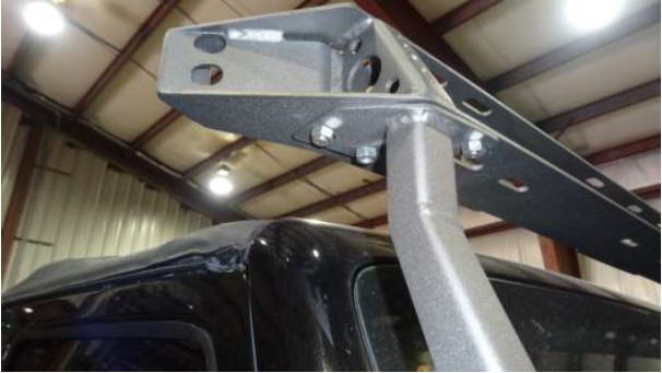
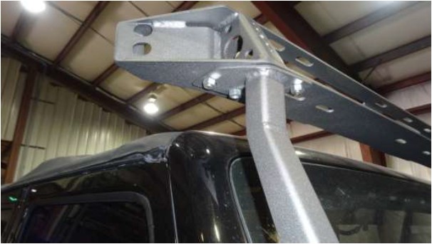
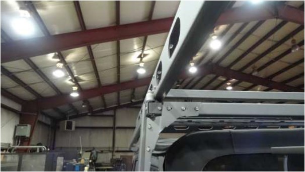
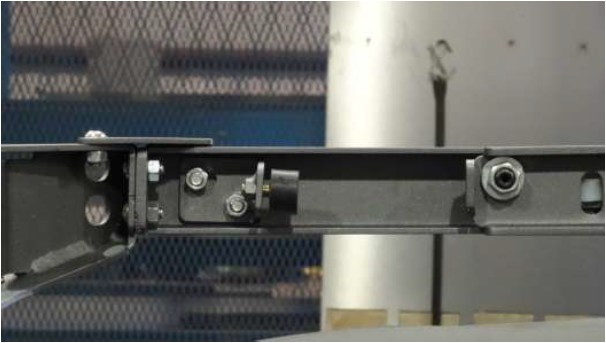
37) The back of the rail will look like the picture above, except without the slotted tab on top. You will need to continually support the rail until the next bracket is placed onto the rail.
38) Using four (4) button head 5/16”x 5/8“ bolts, mount the rear gusset onto the rear upright and the main rail. Leave these four (4) bolts loose as well.
39) Place the rear corner gussets onto the top of the tail light mounts.
40) Place two (2) button head 1/4"x1/2” bolts down into the mount and three (3) button head 5/16”x 3/4" bolts into the rear upright. Again leave all these bolts loose as well. At this point the rack frame work should support itself but still be easily moveable.

41) Now moving back to the front of the rack. Tighten the four (4) bolts on the front at the windshield mount. Do this on each side.
42) Also tighten the three (3) bolts at the top that mount the front cross-member to each side. Do this for each side as well.
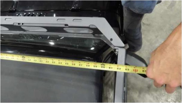
43) Now carefully measure across the top side of the main rails running the length of the jeep. Hook the tape measure on the outside of the opposite side rail.
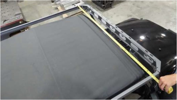
44) IMPORTANT: Measuring across the width of the frame work from outside to outside of the rails the measurement needs to be set at 62-3/4”. This is very important! The rails need to be set at this measurement and tightened. Be sure that the rails are also sitting square. If the rails are misaligned at this point the rack will be difficult to roll open and closed later.
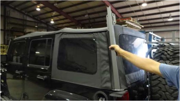
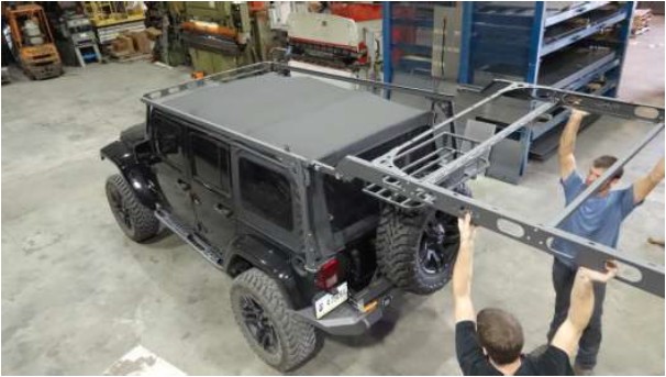
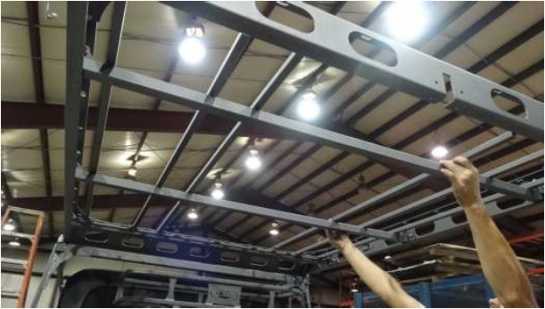
45) With the front of the system tightened it is time to slide the rack itself into the framework. Be sure you are capable of lifting the weight of the rack above your head for a short period of time. The rear framework of the rack should be very adjustable at this point. Carefully slide the rack into the rails. Do not let the rails support the rack yet.
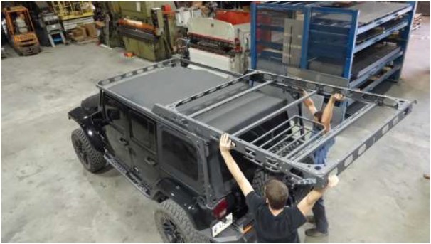
46) Carefully work the rack toward the front of the framework. Push the rack until the back of it is close to the end of the main rails. At this point the rack will support itself. Keep in mind that moving the rack side to side may cause it to fall out of the rails.
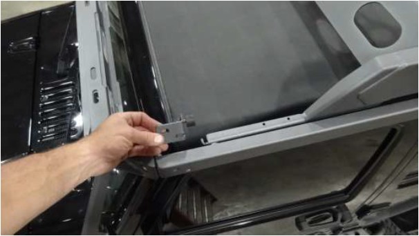
47) Place the rear cross-member between the main rails with larger cut out toward the top. The rear cross-member is made to accept the rear roller system and must have the larger cut out towards the top. Using two (2) button head 5/16”x 3/4" bolts secure the cross-member to the framework on the ends. Align the cross-member to be flush with the ends of the main rails and tighten in place.
48) Orient the rear roller system to match the photo.
49) Lift the rear corner of the rack enough to slide the roller system into the front side of the rear cross member.
50) Fasten the rear roller system inside the rear cross-member. Only use the far outside bolt hole at this point as shown in the next photo. Use one (1) button head 5/16” x 3/4" bolt per side.
51) When the rollers are installed they should look like the above photo. Notice the location of the bolt.
52) Mount the upper corner gussets to the rear cross-member and the rear upright. Use two (2) button head 5/16” X 5/8” for the side two bolts. Use three (3) button head 5/16” x 3/4" bolts for the top three (3) existing holes. Do not tighten any of the bolts yet.
53) Now tighten all of the bolts related to the rear mounting point. Be sure to double check all bolts. The only bolts that should be loose at this point are the six (6) across the top in the very back. Every other bolt installed up to this point needs to be tight.
54) The roller system is adjustable to accomadate minor variations in the rack width. Before tightening any of the bolts roll the rack open and closed keeping an eye on the rollers. A minimal gap is necessary so that the rack rolls as easily as possible. The rollers are to guide the rack and are not intended to be pressed tightly against the sides of the rack. Tighten the six (6) bolts once the rollers are adjusted.
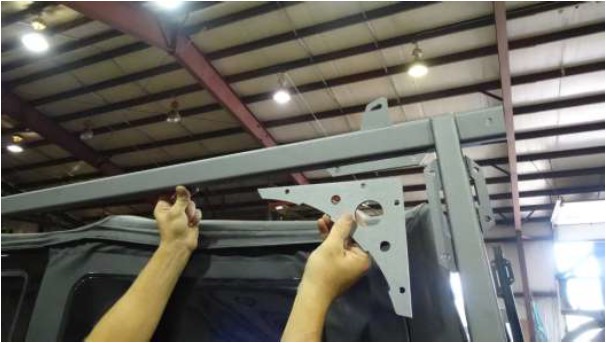
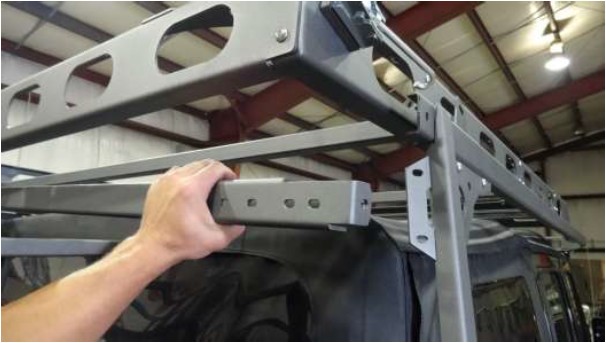
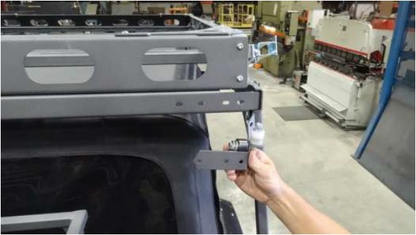
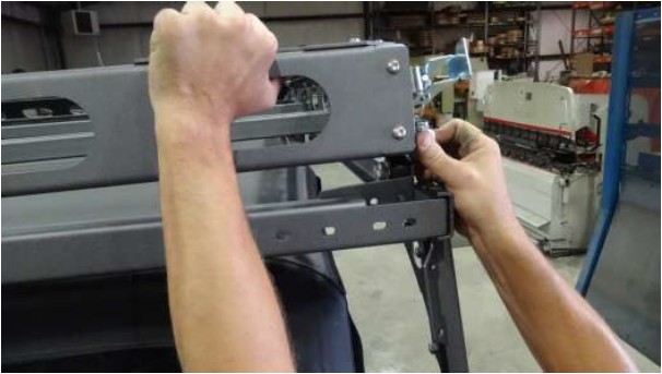
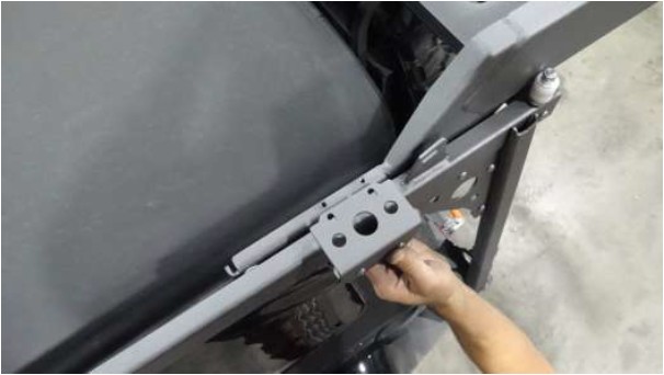
55) Moving back to the front place the small “L” shaped bracket with two slots so that it will fit into the main rail and line up with the existing holes in the rail.
56) The bracket from the previous step will bolted with the bracket shown in the picture above. Use two (2) button head 5/16” X 3/4” bolts through the side of the brackets. The bolts will pass through the bracket then the main rail and finally through the “L” shaped bracket from the previous step.
57) The inside will look like the picture above. Thread the rubber isolator onto the bracket inside the rail. This will need to be adjusted so that when the rack is latched closed it will be flush with the rear cross-member.
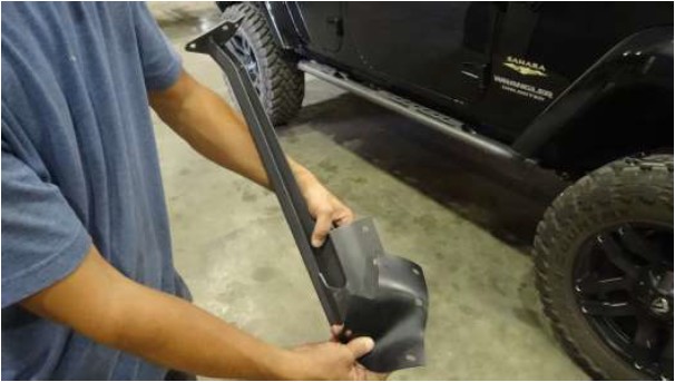
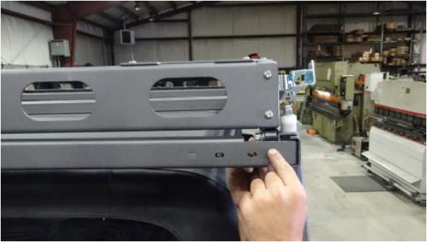
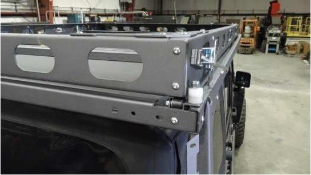
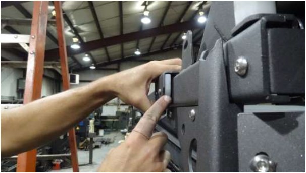
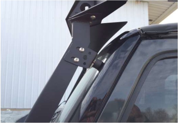
58) The bracket with the plastic attached to it needs to be mounted to the top side of the sliding part of the rack.
59) Be sure there is a slight gap on this bracket. The bracket is there so that the rollers can never get out of the track under any circumstance. If these brackets are not properly adjusted they will act like brake shoes instead of rail guides.
60) Place the floor tubes in over the top of the rack. Spacing for these bars is completely up to the user. Bars can be spaced evenly across the span of the floor or consolidated in one area for carrying something specific. These tubes are mounted using two (2) hex head 1/4"x 3/4” bolts per tube.
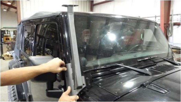
61) Thread the rubber isolators into the L-shaped bracket pictured above and mount the bracket to vertical uprights in front of the window. You will notice the brackets are angled to match the pitch of the window. Adjust brackets so that there is pressure between the window frame and rubber isolator. This will dampen any remaining movement within the rack frame.
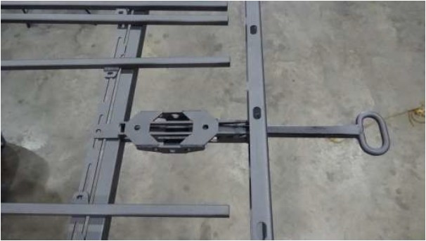
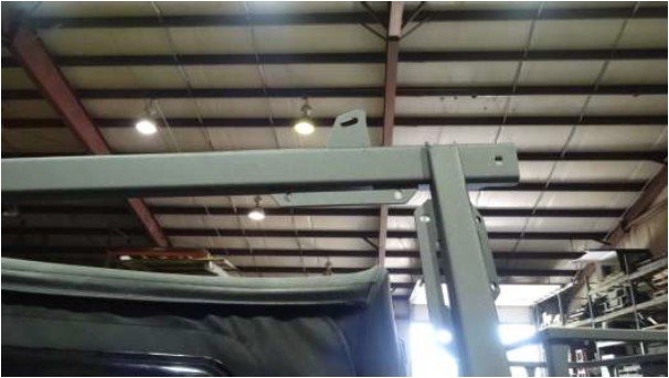
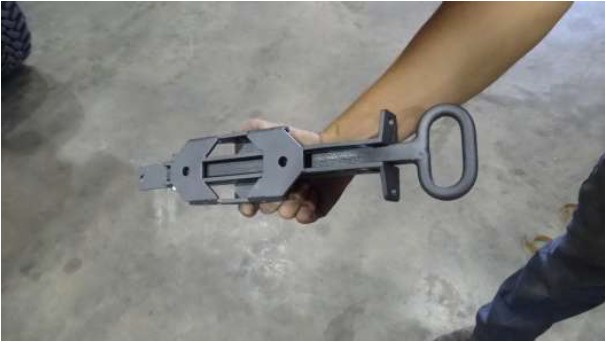
62) The handle mechanism will need to be placed with the two large holes toward the top.
63) Feed the mechanism up at an angle through the back of the rack and over the top of the rear cross bar.
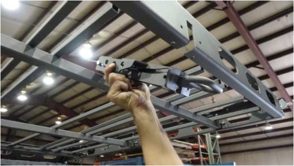
64) The handle will bolt above the rear cross bar and in front of the back of the rack. The front bolt will be one (1) hex head 1/4”x 3/4” and the two (2) rear bolts will be button head 5/16”x3/4”.