
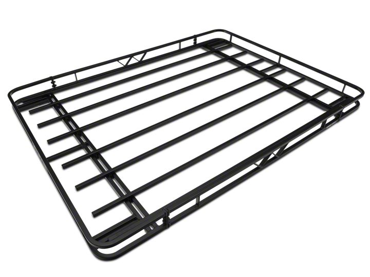
How to Install Garvin Expedition Rack On Your 07-14 Wrangler
Shop Parts in this Guide

Installation Instructions
1. Remove both rear tail light assemblies. Remove the two inboard screws on the tail lights and remove lights and disconnect wiring. Set the lights aside, all the rear brackets and support bracket installations are done through the light body access hole.
2. Remove the license plate and housing assembly using a 7mm socket. Reach inside access hole and push on clips for housing assembly to come off. Disconnect or cut license light wires, they will reconnect later in the installation. Rear bumper may have to be loosened and lowered slightly to gain access to the two lower 7mm head screws.
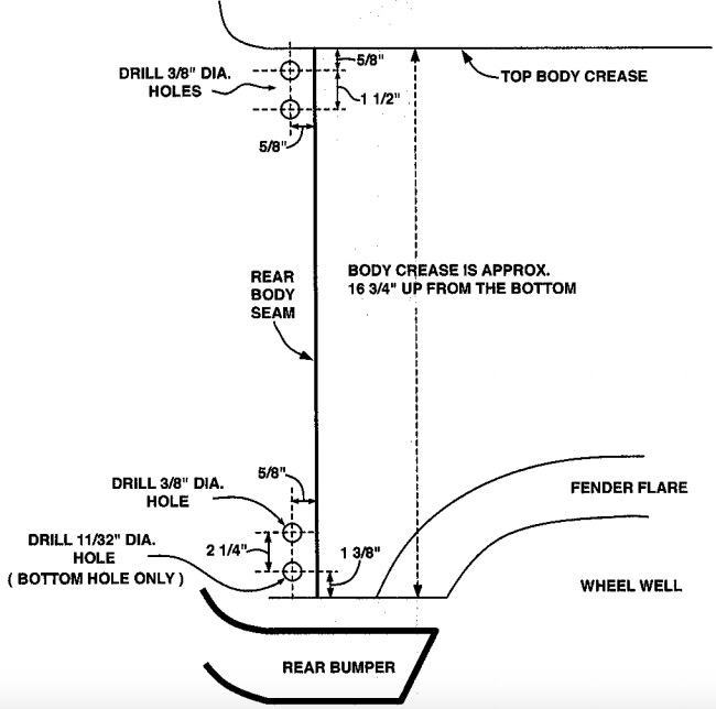
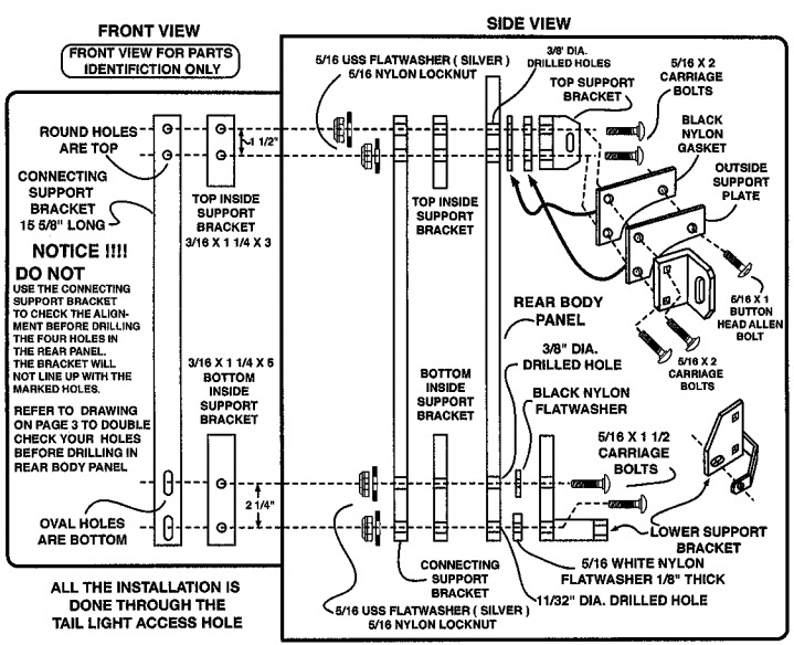
3. Measure and mark holes to be drilled, refer to page 3. Double check measurements before drilling. Drill holes
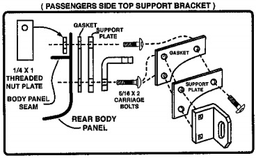
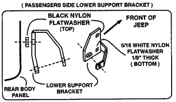
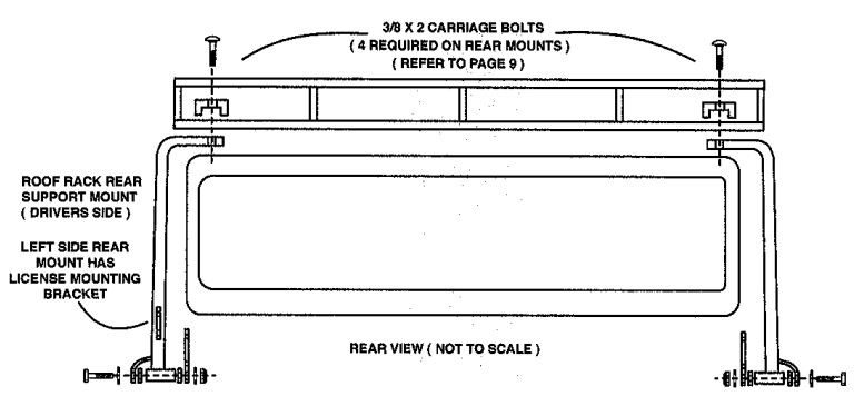
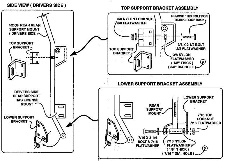
4. Install rear mount support brackets and inside support brackets, as shown on page 3A and 4.
5. Install rear supports to mounting brackets as shown on page 5.
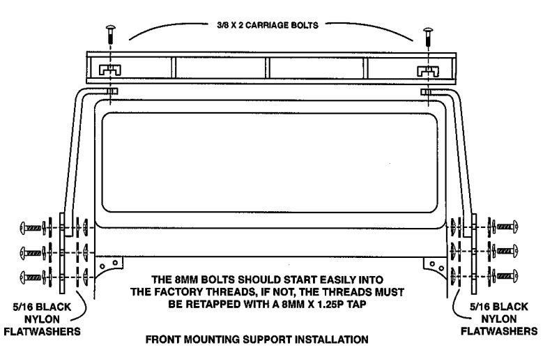
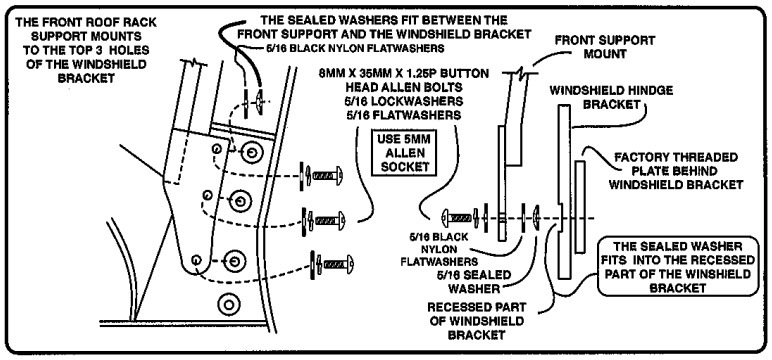
6. Remove the top three bolts on each side of the windshield brackets (use T-40 socket) and install both front supports using hardware provided, as shown on page 6. Slightly tighten to hold in place. Make sure all sealed washers fit into the recess.
7. Assemble roof rack as shown on page 7.
8. Install floowing as shown on page 8.
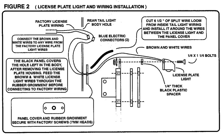
9. Install black panel cover, course side out, and grommet, re-using the 7mm head factory screws, as shown on page 10.
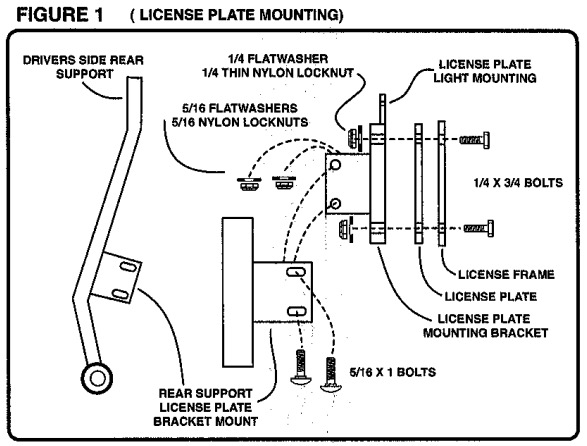
10. For ease of assembly, install license plate bracket to drivers side rear support, as shown on page 10, figure 1. Install license plate and license cover (if applicable)
11. Install license plate light assembly as shown on page 10, figure 2. Feed wires through rubber grommet and back out through tail light access hole. Cut wire to desired length and connect to factory wiring, as shown on page 10, figure 2. Check license light operation.
12. Re-install tail light assemblies.
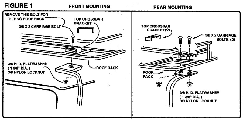
13. With some help, set the assembled roof rack and flooring on the four roof rack support arms and secure, as shown on page 9, figure 1.
14. Re-check alignment and tighten all mounting hardware.
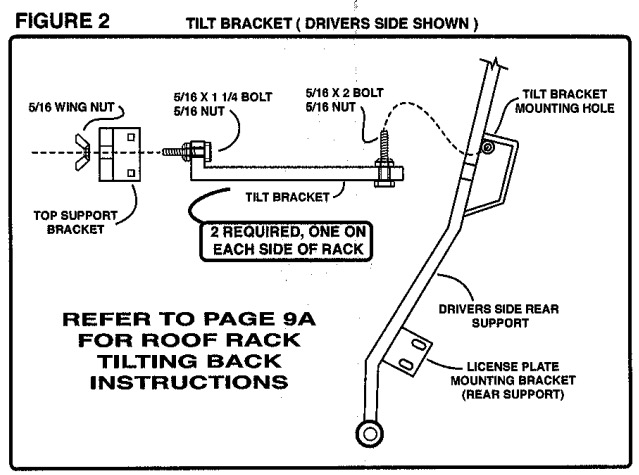
15. Assemble thte tilt brackets as shown on page 9, figure 2. Refer to page 9A for tilting instructions.
16. This type of product is always subject to nicks and scratches. Touch-up all nicks and scratches with a rust preventative satin black paint. Failure to touch-up will result in rusting. If rust is visible clean and touch up.
17. CAUTION!!! LOADING AND WEIGHT CAPACITY, use common sense when loading items on this roof rack. The roof rack will support more weight that the vehicle roof mounting will safely support. Use manufacturers weight limits as a guide for loading this roof rack.


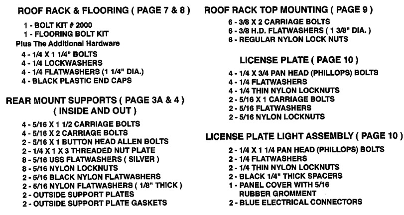
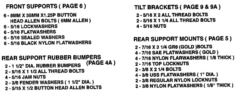
HARDWARE KITS

PUT MASTING TAPE OVER THE AREA TO BE MARKED AND DRILLED THEN MARK AND DRILL A SMALL 1/8" DIA. PILOT HOLE FIRST, THEN ENLARGE THE HOLE TO THE PROPER SIZE
PASSENGERS SIDE SHOWN

PASSENGERS SIDE SHOWN
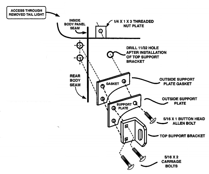
INSTRUCTIONS
1 - LAYOUT AND DRILL HOLES IN BODY REFER TO PAGE 3.
2 - INSTALL TOP SUPPORT, SUPPORT PLATE AND GASKET AS SHOWN ON PAGE 3A & 4.
3 - ALIGN SUPPORT BRACKET AND TIGHTEN THE TWO MOUNTING BOLTS ( 5/16 X 2 CARRIAGE )
4 - USING THE HOLE IN THE OUTSIDE SUPPORT PLATE AS A GUIDE, DRILL A 11/32" DIA. THROUGH THE BODY.
5 - SECURE AS SHOWN, USING 5/16 ALLEN BOLT AND THREADED NUT PLATE
6 - TIGHTEN ALL FASTENERS.
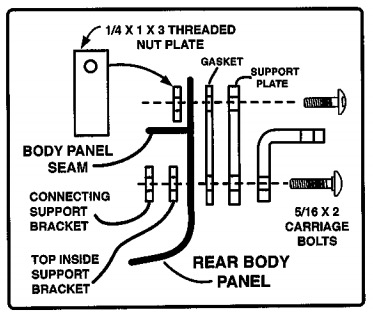

TOP VIEW
TOP VIEW

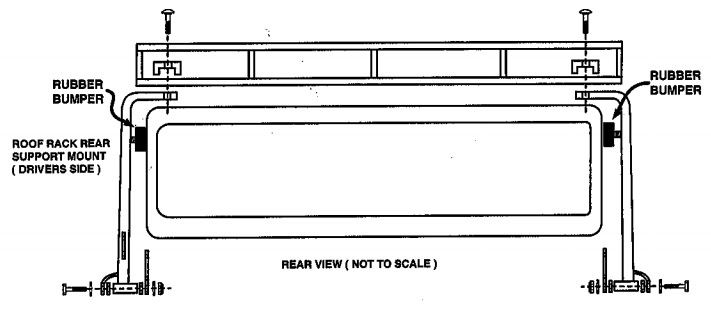
THIS SUPPLEMENT INSTRUCTION SHEET IS ONLY FOR THE JK HARDTOP MODELS
1 - SCREW RUBBER BUMPER ASSEMBLY INTO THE THREADED COUPLING NUT THAT IS WELDED ON THE REAR SUPPORT ARMS. THIS SHOULD BE DONE BEFORE INSTALLING REAR SUPPORTS TO JEEP.
2 - AFTER COMPLETING THE ROOF RACK INSTALLATION, ADJUST THE RUBBER BUMPER SLIGHTLY AGAINST THE TOP AND SECURE WITH THE LOCKING JAM NUT.
PARTS LIST
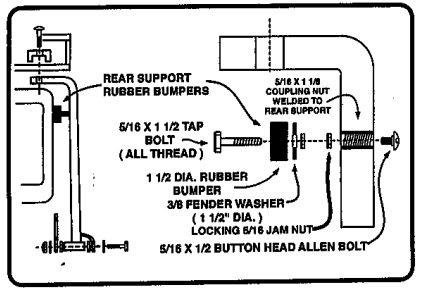
REAR SUPPORT RUBBER BUMPERS
2 - 1 1/2" DIA. RUBBER BUMPERS
2 - 5/16 X 1 1/2 ALL THREAD BOLTS
4 - 5/16 JAM NUTS
2 - 3/8 FENDER WASHERS ( 1 1/2" DIA. )
2 - 5/16 X 1/2 BUTTON HEAD ALLEN BOLTS



PARTS LIST
ROOF RACK ASSEMBLY
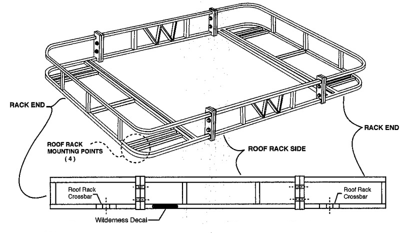
1. Assemble roof rack ends to roof rack sides as shown in figures I and J.
2. Align and tighten all fasteners.
3. Roof rack flooring and vehicle mounting are shown in their respective installation instructions.
CAUTION!!! LOADING and WEIGHT CAPACITY
1. Use common sense when loading items on this roof rack.
2. The roof rack will support more weight than the vehicle roof mounting will safely support.
3. As a general rule up to 300 Lbs. evenly distributed is a safe load for this rack.
FIGURE I
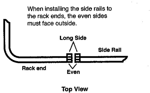
FIGURE J


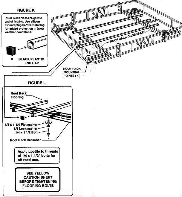
THE 8 FLOOR PIECES THAT ARE SUPPLIED WITH THIS KIT, MOUNT ON THE TOP OF THE ROOF RACK CROSSBARS AS SHOWN. ADDITIONAL FLOOR PIECES CAN BE PURCHASED FROM GARVIN INDUSTRIES.
PARTS LIST
8 - FLOOR PIECES (66" )
1 - FLOORING BOLT KIT
PLUS THE ADDITIONAL HARDWARE
4 - 1/4 X 1 1/4" BOLTS
4 - 1/4 LOCKWASHERS
4 - 1/4 FLATWASHERS (1 1/4" DIA.)
4 - BLACK PLASTIC END CAPS
INSTALLATION INSTRUCTIONS
1 - INSTALL BLACK PLASTIC END CAPS IN FLOOR ENDS (FIGURE K)
2 - INSTALL FLOORS TO ROOF RACK CROSSBARS (FIGURE L)
3 - START ALL BOLTS IN FLOORING (FIGURE B), LEAVE BOLTS LOOSE, EVENLY SPACE FLOORS ON ROOF RACK.
4 - ALIGN FLOORS AND THEN READ THE YELLOW CAUTION SHEET (ENCLOSED) BEFORE TIGHTENING 1/4 X 1 1/2" BOLTS.
5 - WHEN SPACING THE TWO (2) OUTBOARD FLOORS, MAKE SURE THEY CLEAR THE ROOF RACK MOUNTING POINTS AS SHOWN IN THE DRAWING ABOVE.
6 - WHEN INSTALLING THE SPARE TIRE CARRIER PART #29880, THE TWO MIDDLE FLOORS MUST BE SPACED SO THE OUTSIDE MEASUREMENT IS 5 3/8".
CAUTION!!!
DO NOT MOUNT A TIRE AND WHEEL ASSEMBLY LARGER THAN 31" ON THIS RACK.
IF YOU MOUNT A SPARE ON THE RACK, MOUNT THE TIRE OVER THE CROSSBAR, NOT IN THE MIDDLE OF THE RACK.
DO NOT DRIVE OFF ROAD IN EXTREME CONDITIONS WITH A SPARE TIRE IN THE TACK.
A QUALITY SWING-A-WAY TIRE CARRIER AND BUMPER ASSEMBLY, SUCH AS THE WILDERNESS PART #34900 IS HIGHLY RECOMMENDED FOR ALL TIRED OVER 31" WHILE DRIVING IN ROUGH OFF ROAD CONDITIONS.


1 - ROOF RACK MUST BE EMPTY
2 - REMOVE FRONT TOP ROOF RACK MOUNTING BOLTS, REFER TO PAGE 9 FIGURE 1
3 - REMOVE TOP SUPPORT BOLTS ON BOTH REAR SUPPORTS, REFER TO PAGE 5
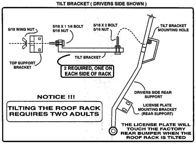
4 - EACH PERSON GRABS THE ROOF RACK AND THE REAR SUPPORT ON EACH SIDE AND PULLS BACK ON THE RACK, WHEN THE RACK IS HIGH ENOUGH IT WILL SOMEWHAT BALANCE ITSELF. HOLD THE RACK UP WHILE INSTALLING THE TILT BRACKETS.
5 - INSTALL THE TILT BRACKETS IN THE ROUND HOLES IN THE REAR SUPPORTS, REFER TO ABOVE DRAWING
6 - SLOWLY LET THE RACK GO FORWARD AS YOU GUIDE THE TILT BRACKET BOLT INTO THE TOP SUPPORT BRACKET AS SHOWN IN ABOVE DRAWING.
7 - SECURE WITH THE 5/16 WING NUT.
8 - TO LET THE ROOF RACK BACK DOWN, REVERSE THE PROCEDURE, AND LET THE RACK DOWN SLOWLY.
9 - RE-SECURE THE ROOF RACK TO THE MOUNTING SUPPORTS.

