 FREE 1 to 3-Day Delivery on Orders $119+ Details
Talk to a Wrangler Sales Tech
1-877-870-8556
M-F 8:30A-11P, Sat-Sun 8:30A-9P

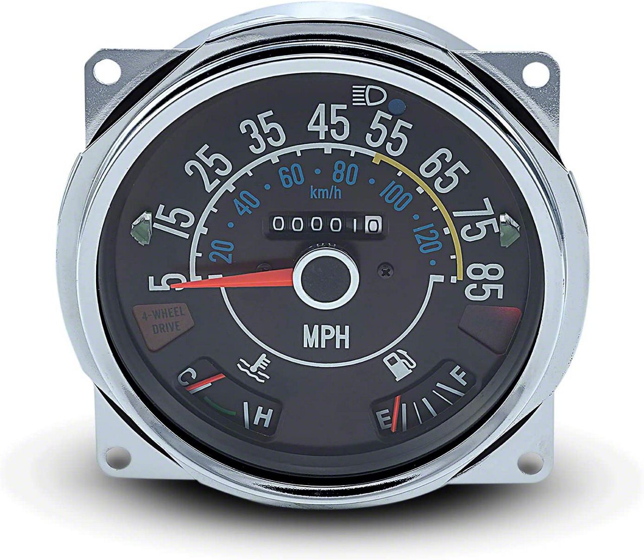
Fuel and Temperature Gauges Troubleshooting 1972-1986 Jeep CJ's
Jeep CJ gauges, typical of older Jeeps, will degrade over time. Here are simple techniques to troubleshoot these gauges and prolong the life of the OEM parts. If your temperature gauge isn't moving or you're uncertain about your fuel gauge's accuracy, these tips will help.
Understanding the Fuel and Temperature Gauges
The gauges are laid out from left to right, with each having wiring terminals and a large jumper/regulator strap between them.
-
Fuel Gauge Terminals:
- S: Connected via a pink wire to the fuel sender.
- A: 12V side of the jumper/regulator strap.
- I: Connected via a red wire to the 12V ignition.
-
Temperature Gauge Terminals:
- A: 5V side of the jumper/regulator strap.
- S: Connected via a purple wire to the temperature sender.
Back Side of Speedometer with Fuel and Temp Gauge
The jumper/regulator strap runs from a voltage regulator inside the fuel gauge (terminal A) to the temperature gauge (terminal A). A reading at the temperature gauge's terminal A should be approximately 5 volts. A 12V reading indicates a faulty regulator.
The meter movements in the gauges are dampened to prevent the needle from bouncing due to the sender's variable resistance.
Fuel Gauge Resistance Readings
- S to Ground: 68-72 ohms
- S to I: 19-21 ohms
- S to A: 19-21 ohms
- I to A: Zero
- I to Ground: 49-51 ohms
- A to Ground: 49-51 ohms
The fuel sending unit is hard to access without dropping the tank but can be tested with an ohmmeter. Resistance readings should be:
- Empty: 73 ohms
- Half Tank: 23 ohms
- Full: 10 ohms
Temperature Gauge Resistance Readings
- S to A: 19-21 ohms
Measure the voltage between the A terminal of the Temp gauge and ground. If it reads 12 volts, the Jumper Strip/Regulator is bad. The sending unit resistance should vary with temperature, with higher resistance at colder temperatures.
Understanding the Oil Pressure Gauge
- S Terminal (left): Purple wire from sender
- Middle Terminal: Black wire (Ground)
- Right Terminal: Red wire (Ignition-on hot 12v)
To test, momentarily short the wire from the sender to the ground. If the gauge reads 80 psi, the sender is functional.
Understanding the Voltmeter Gauge
- GND Terminal (left): Black wire (Ground)
- Terminal (right): Red wire (Ignition-on hot 12v)
Connect 12 volts to the (+) terminal and ground to the (-) terminal. If the gauge shows no activity, it's likely defective.
Conclusion
Replacing gauges is often more cost-effective than extensive testing due to their relatively low cost. This ensures reliable readings and proper vehicle operation.
This format should help in understanding and troubleshooting the gauges more efficiently.