
How to Install Daystar 2.75 in. Comfort Ride Coil Spacer & Body Mount Lift Kit (97-06 Wrangler TJ) on your Jeep Wrangler
Installation Time
2 hours
Tools Required
- Floor Jack
- 6x4 box of wood
- Drill
- Hand tools
- Vise
- Hammer
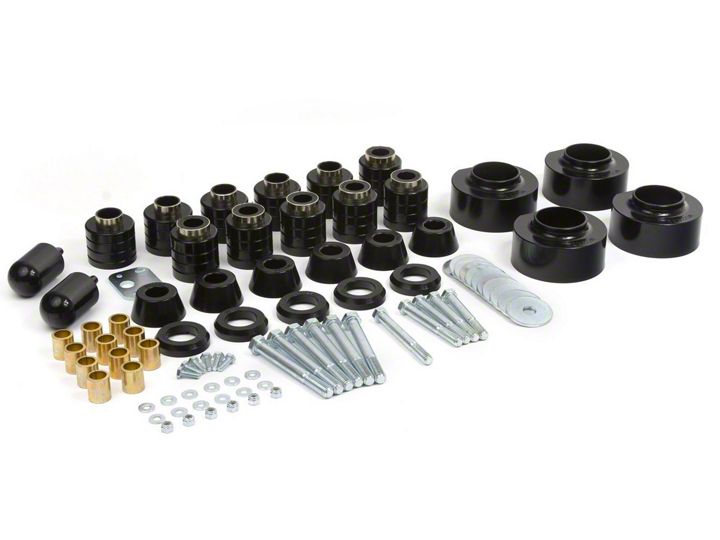
Shop Parts in this Guide
Thank you for choosing Daystar Products
Daystar recommends a certified technician install this system. In addition to
these instruction , professional knowledge of disassemble/reassembly procedures as well as post instructions checks must be known. Attempts to install this system without this knowledge and expertise may jeopardize the integrity and/or operating of the vehicle.
Please read all the instructions before beginning the installation. Check the kit
hardware against the parts list. Be sure you have all the needed parts and understand where they go. If anything is missing , do not proceed with the installation, call Daystar Products to obtain needed items.
Product Use Information
As a general rule, the taller a vehicle is the easier it will roll. We strongly recommend , because of rollover possibility, that Seat belts and shoulder harness be worn at all times. Avoid situations where a side rollover may occur.
Braking performance and capabilities are decreased when significantly large/
heavier tires and wheels are used. Take this into consideration while driving, Also , speedometer recalibration is necessary when larger tires are installed.
Do no add, alter, or fabricate any factory or after-market parts which increase vehicle height over the intended height of the Daystar Product purchased. Mixing component brands, lifts, and/or combining body lift with suspension lift voids all warranties. Daystar makes no claims regarding lifting devices and excludes any and all implied claims. We will not be responsible for any products
Notice to Dealer and Vehicle Owner
Any vehicle equipped with any Daystar Product must have the “Warning to driver”
decal installed on the sun visor or dash. The decal is to act a constant reminder for
whoever is operating the vehicle of its unique handling characteristics. INSTALLING DEALER— Its is your responsibility to install the warning decal and forward these instructions on too the vehicle owner for review and to be kept in the vehicle for service life.
After installation occurs, a qualified alignment facility is required to align the vehicle to factory specs.
BODY MOUNT LOCATION
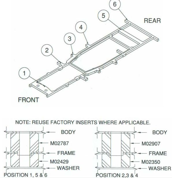
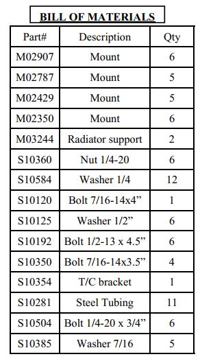
10. Once all new mounts are in place, you may re-torque all bolts to factory specs. Do not over tighten bolts.
11. PLASTIC RADIATOR FAN SHROUD: Drill holes large enough for new ¼” bolts 1” lower than original hole in the radiator bracket that shroud bolts to and re-bolt shroud using the 4 new ¼” bolts, nuts and washers provided in the kit. Make sure fan clears lower portion of fan shroud. It may be necessary to trim fan shroud around lower radiator hose. You may also install Daystar part no. KJ01005: 1” Lift Motor Mounts.
12. Remove the radiator supports on each side and Install the new supports.
13. Before starting engine, check fan for clearance of all lines and wires to make sure they are free and clear.
Installation step
1. PLASTIC RADIATOR FAN SHROUD: The fan will hit the lower portion of the fan shroud. Before starting installation, Remove the 4 screws that hold the fan shroud to the radiator allowing the fan shroud to be lowered once body lift is completed. Make sure fan is clear of fan shroud before beginning. See instruction No. 13.
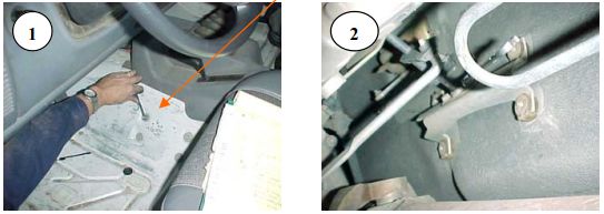
2. TRANSFER CASE SHIFT LEVER DROP: Disconnect shift lever bracket by removing carpet on driver’s side of vehicle. Remove four 10mm screws on transmission side of driver’s side floor ( 1 ), just below transfer case shift lever. Remove transmission shift linkage bracket located under vehicle ( 2 ) . Remove the two 10mm screws on shift linkage bracket.
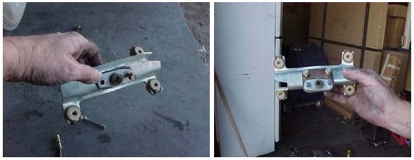
3. Install transmission linkage lowering plate to stock transmission linkage bracket with 2 each ¼” machine bolts, lock washers and nuts (Included in kit). The bracket faces down with large center hole provided for linkage shaft to be inserted.
4. Reinstall transmission linkage bracket to body and tighten down. You may have to adjust the shifter linkage.
5. Loosen body mount bolts on one side of vehicle and remove bolts from opposite side using a 5/8” socket for positions 1,5 and 6 ( body mount location chart ) and a ¾” socket for positions 2, 3 and 4. Use a long extension to remove mounts next to gas tank. Place 2x4 between jack and body to spread out load and jack up body on the side you have removed the bolts from just far enough to remove mounts. The bolts on the opposite side will help ensure that the body does not shift. CAUTION: Open Hood while jacking up the body to make sure that the fan doesn’t hit the shroud. Also, watch that hoses and wires are not stretched. The dip-stick head can be pinched so remove dipstick while doing installation. When lifting the side of the vehicle that the fuel filler is on keep a close eye not to stretch, tear or pull too far on the hose connection.)
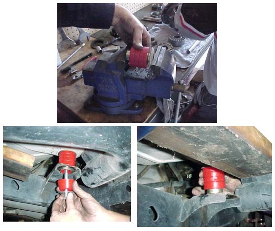
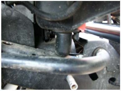
6. Remove factory mounts 1 at a time and remove stock steel insert
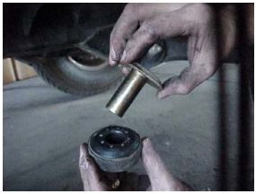
7. Insert stock steel inserts inside top portion of body lift spacer (Note: It fits tight, you may have to use a vise.)
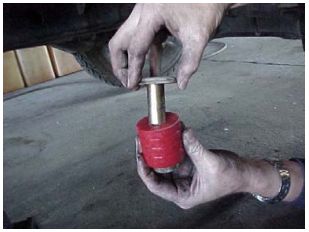
8. Insert 7/8” OD x 1” Long tube (Part No S10281 Included in kit) into lower portion of body lift spacer. (This tube is a crush sleeve to eliminate over-torque of polyurethane mounts)
9. Jack up the body using a 2x4 under one side of the body for support just high enough to insert new body lift spacers. If the steel collar on new mounts will not insert in frame holes, you may have to file out frame mount hole slightly to install spacer. Repeat on opposite side.
