
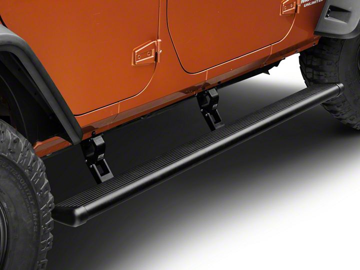
How to Install Amp Research PowerStep on your Wrangler
Shop Parts in this Guide
Step 1: Locate rear linkage installation position in front of rear body mount.
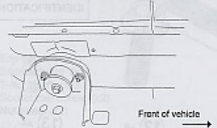
Step 2: Install adaptor as shown.
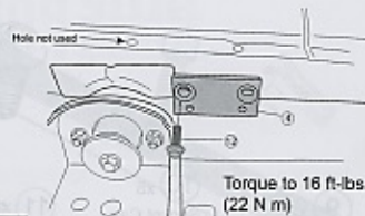
Step 3: Install idler linkage.

Step 4: Install U nute under vehicle, middle of front door for front motor linkage as shown.
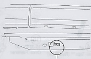
Step 5: Slide motor assembly onto drive shaft and mounting bosses of driving linkage assembly. Use flathead socket head cap screw on the inner location. Next use hex bolt and washer on outer location and tighten to 8 ft-lbs/11 Nm.

Step 6: Install front motor linkage with motor. Install light bracket on front side of linkage as in step 3.
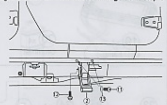
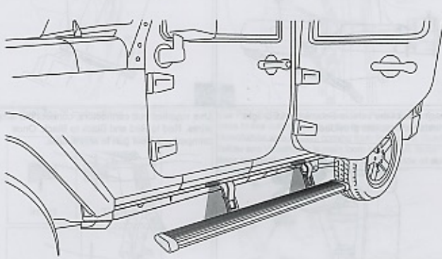
Step 7: Mount step extrusion to linkage assemblies. Line up t-nuts in step assembly with slots in lower mounts of linkage assemblies. Fasten loosely to allow for adjustments.
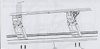
Step 8: Line up rear of step extrusion with rear fender well.
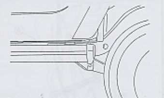
Step 9: Tighten 4 socket cap screws with 3/16" allen wrench. Torque to 10 ft.-lbs.
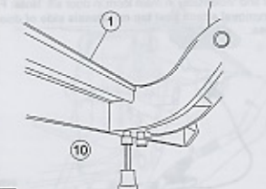
Step 10: Remove fuse from Power Step wire harness.
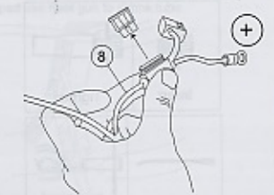
Step 11: Install controller on passenger side at firewall. Secure with 11" cable ties. connect red wire to positive battery terminal and black wire to negative battery terminal.
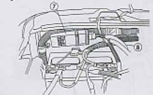
Step 12: Route longest leg of wire harness across fire wall to driver side and under vehicle outside of frame rail. Route shortest leg of wire harness down fire wall and outside of frame rail on passenger side.
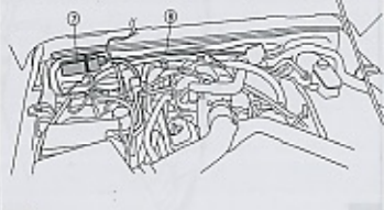
Step 13: Remove passenger side front door sill.
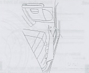
Step 14: Lift carpet. Slit rubber grommet and pass trigger wires through grommet in floor into passenger compartment.
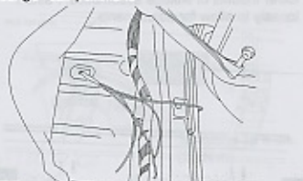
Step 15: Insert, tighten and strip Posi-Tap.

Step 16: Use Posi-Tap connectors to connect Power STep trigger wires to like colored wires in the facotry system as shown.
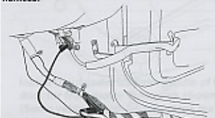
Step 17: Remove driver side door sill and pull up carpet.
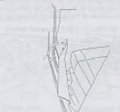
Step 18: Route violeet wire under carpet to driver side door sill and connect to violet wire coming from door as shown.
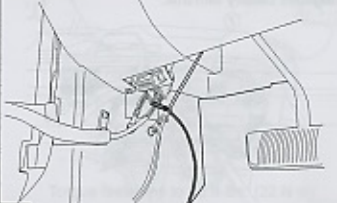
Step 19: Insert plug from wire harness onto motor. Slide rubber grommet on wire harness into slot of motor cover. Insert motor cover onto motor. Slide motor assembly onto drive shaft and mounting boasses of driving linkage assembly. Use electrical tape to cover any exposed wire from the motor.
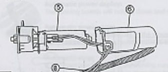
Step 20: Insert plastic push pin rivets in mounting holes of motor cover. Use pliers to ease installation.
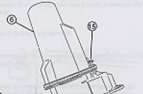
Step 21: On each side of the vehicle secure the LED light onto installed brackets provided.
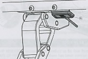
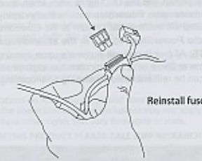
Step 22: Use supplied butt connectors, connect the lamp wires. Red to red and black to black. Once crimped use heat gun to shrink tube.
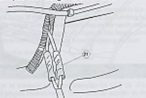
Step 23: Reinstall fuse.
