

Top Sellers for Wrangler
How to Install AFE Momentum GT Stage-2 Pro 5R Intake System on your Jeep Wrangler
Installation Time
1 hours
Tools Required
- 8mm nut driver
- 10mm nut driver
- 7/16” nut driver
- 1/4” driver
- 10mm deep socket
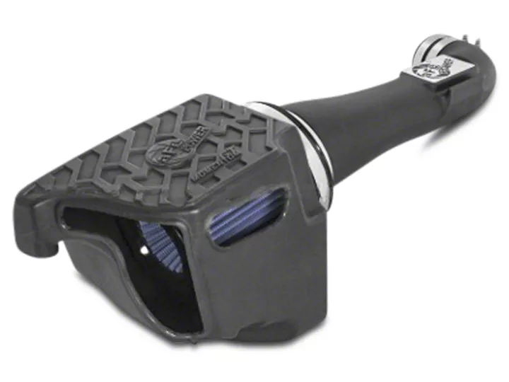
Shop Parts in this Guide
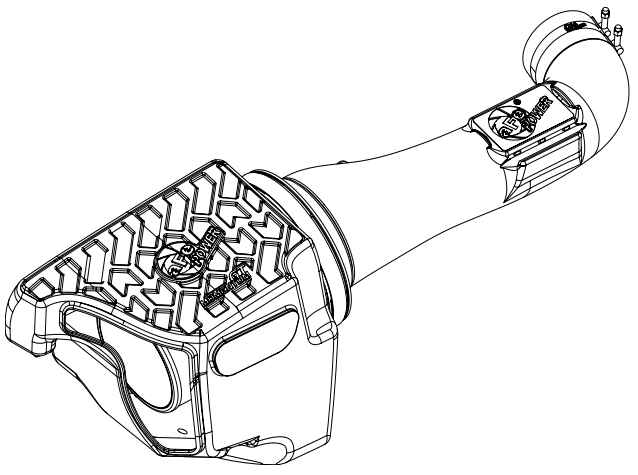
Instruction Manual
• Please read the entire instruction manual before proceeding.
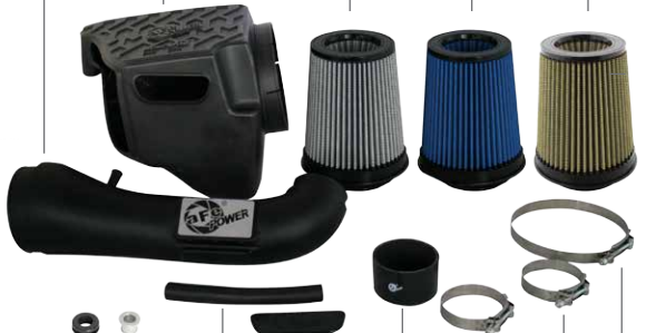
• Ensure all components listed are present.
• If you are missing any of the components, call customer support at 951-493-7100.
• Ensure you have all necessary tools before proceeding.
• Do not attempt to work on your vehicle when the engine is hot.
• Disconnect the negative battery terminal before proceeding.
• Retain factory parts for future use.
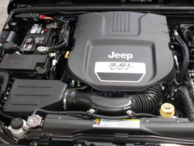
Refer to Figure A for Step 1
Step 1: Remove the engine cover by lifting firmly out of the vehicle.
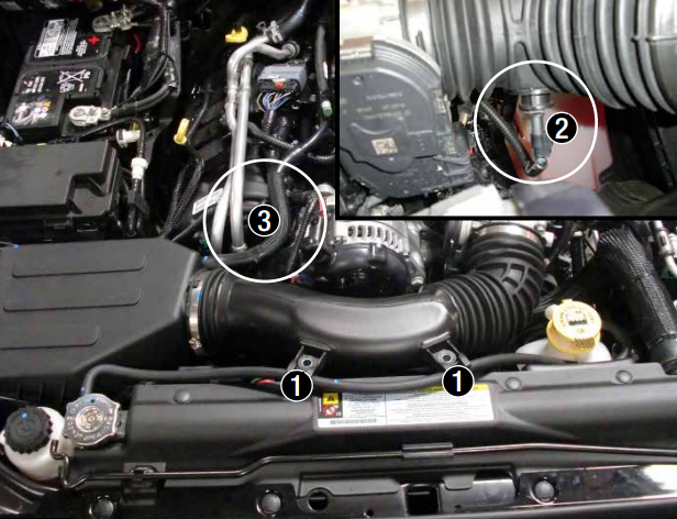
Refer to Figure B for Steps 2-6
Step 2: Remove the two 10mm bolts from the intake tube. 1
Step 3: Disconnect the temp sensor wire harness. 2
Step 4: Loosen the hose clamp at the throttle body.
Step 5: Completely remove the small section of crankcase vent (CCV) hose. It should be pulled off of the air filter housing and the tube to the engine. 3
Step 6: Remove the stock intake tube, and air filter housing by pulling straight up and out of the vehicle.
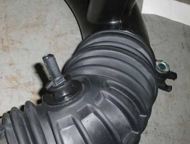
Refer to Figure C for Step 7
Step 7: Twist the temp sensor about 45 degrees counter-clockwise and pull it straight up to remove from stock tube.
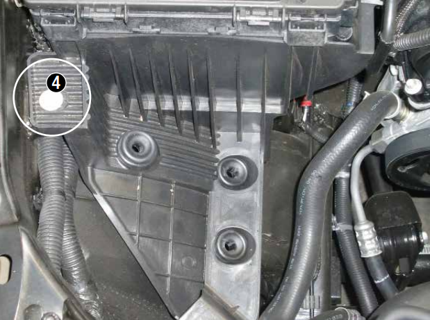
Refer to Figure D for Step 8
Step 8: Remove the 10mm bolt that secures the plastic tray onto the inner fender, but do not remove the plastic tray. 4 This screw will be reused in later step.
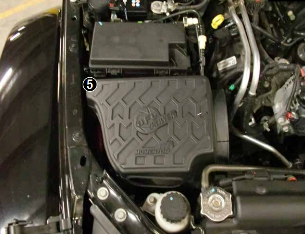
Refer to Figure E for Step 9
Step 9: Install the housing into the vehicle as shown 5 . Secure the hosuing using the stock screw removed in Step 8.
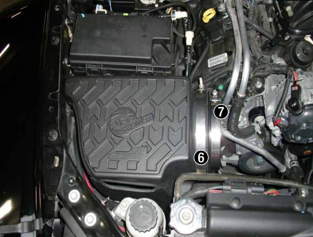
Refer to Figure F for Steps 10-11
Step 10: Slide 7.00” clamp over flange on housing 6 .
Step 11: Install the air filter into the housing and slide clamp 5.50” over end of filter 7 .
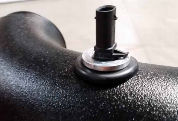
Refer to Figure G for Steps 12-13
Step 12: Insert the billet adaptor into the grommet.
Step 13: Insert the factory temp sensor into the billet adaptor and twist 1/8 turn until the plastic tab locks over the small bump on the adaptor.
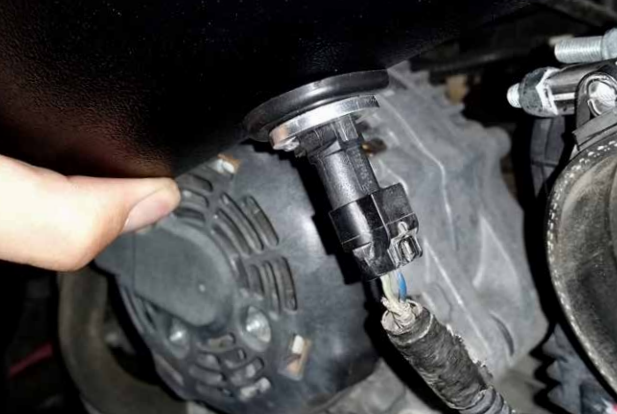
Refer to Figure H for Step 14
Step 14: Plug in the temp sensor harness.
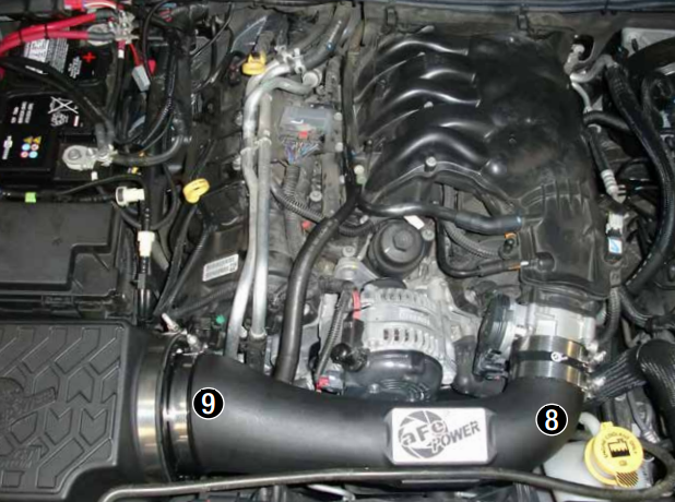
Refer to Figure I for Steps 15-19
Step 15: Place the silicone coupler onto the small end of the intake tube 8 .
Step 16: Place the two 3.50” clamps over the coupler and then drop tube assembly into the filter 9 .
Step 17: Place the larger end of the intake tube into the filter first then slide onto throttle body. Make sure all of the t-bolt clamps are loose at this time in order to install the tube easily.
Step 18: Snap the coolant overflow line into the clip on the front of the aFe intake tube.
Step 19: Install the new CCV hose (Note: use lubricant on the outside of the aFe tube).
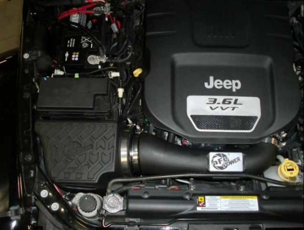
Refer to Figure J for Step 20
Step 20: Tighten all clamps and re-install engine cover. Your install is now complete.
*Verify all connections are secure 100-200 miles after installation


